This thread has been locked.

If you have a related question, please click the "Ask a related question" button in the top right corner. The newly created question will be automatically linked to this question.

XTR117: Two XTR117 with acceptable error.

Part Number: XTR117
Other Parts Discussed in Thread: XTR111

Hi,

i'm updating my transmiter to work with two outputs like this one

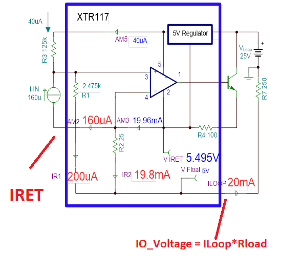
As i'm already using XTR117 i'm trying to (almost giving up) to manage using it.

In the circuit above i'm accepting 1% error of the current going to DAC_OUT2 (actually i could programatically compensate this error). All the circuit is powered by 5V.

The problem there is that i can't figure it out how to keep Iret from U5 in the same potencial as the Iret from U4, without leting any current in U5's Iret.

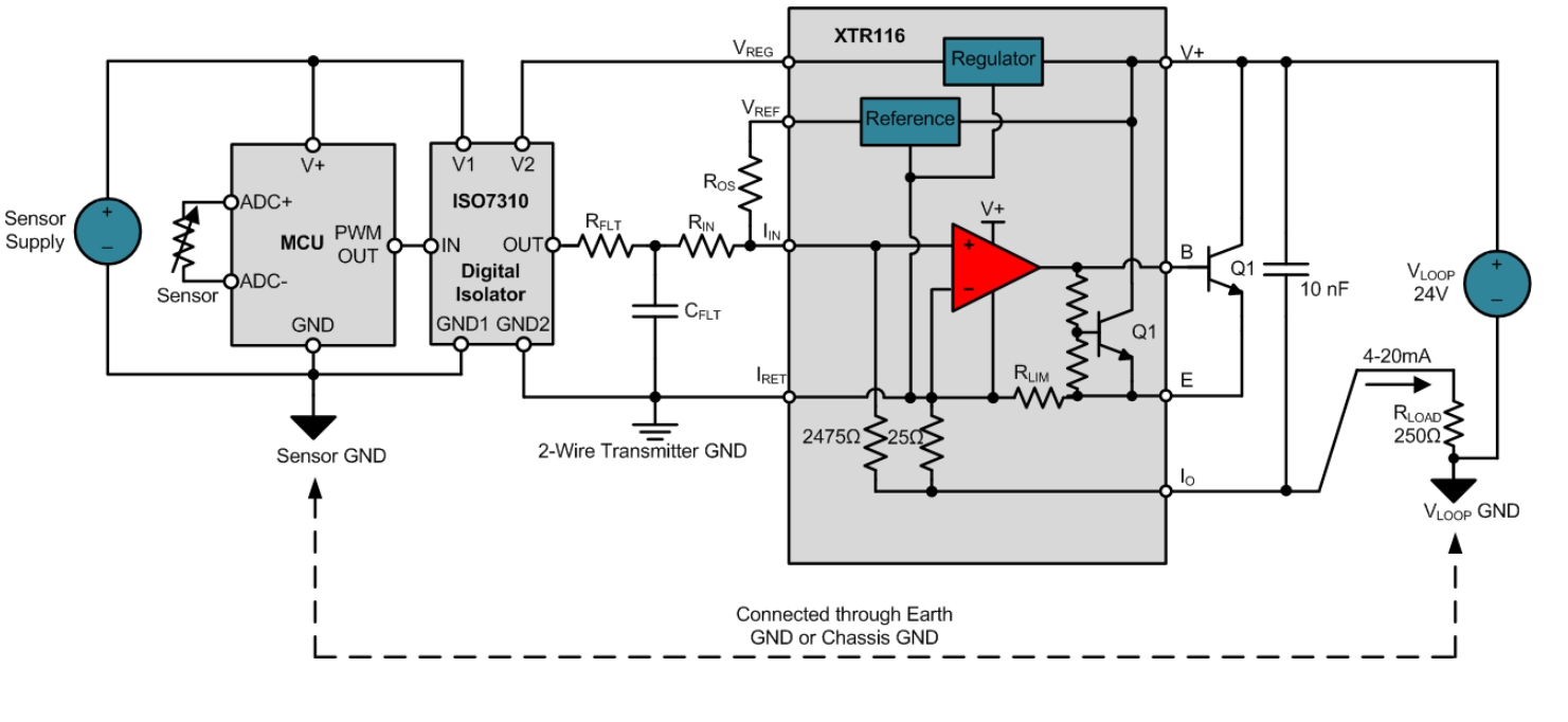
I could use a isolator, but i don't have any current left in the input side, and the prices is going very high in those low quiscient current.

What's my best option? Design all the analog loop circuit? Is there any solution or similar IC that i could work with?

Thanks!

  • Hi Rodrigo,

    The XTR117 is a two-wire transmitter, and as you correctly have pointed out, the IRET has to be independent for each, since the IOUT pin potential for each transmitter is a function of the produced Iout (load current) as shown on the image below. Since the IOUT will have different voltage potential with respect to the loop ground depending on the output current; IRET is required to float to a potential slightly above IOUT, as a function of the transmitter current output and the load resistor.  

    Therefore, unfortunately,  it is not possible to configure the circuit to have multiple DAC circuits feeding multiple XTR117s (2-wire current transmitters) referred to the same IRET. 

    - One option is to use independent DAC circuits for each XTR117, with each DAC connected to each independent IRET. 

    - A second option may be to isolate the DACs as you have mentioned above.

    - Alternatively, you could consider using a 3-wire transmitter such as the XTR111, where all the circuitry is biased with respect to the same loop GND and a multiple channel DAC could be used to drive multiple XTR111s.  However, 3-wire transmitters are in most cases locally powered as discussed on the attached presentation.

     Attached is a presentation that discusses 2-wire vs 3-wire transmitters in detail:

    3678.4-20mA_Basics.pdf

    Below are a couple of blogs that discuss isolation briefly when driving 2-wire transmitters that could be useful.

    2-Wire 4-20mA Sensor Transmitters:  Background + Compliance Voltage
    https://e2e.ti.com/blogs_/b/precisionhub/archive/2014/11/04/two-wire-4-20-ma-transmitters-background-and-common-issues

    2-Wire 4-20mA – IRET Can’t connect to Vloop GND
    https://e2e.ti.com/blogs_/b/precisionhub/archive/2014/12/09/part-2-two-wire-4-20-ma-transmitters-background-and-common-issues

    2-Wire 4-20mA – Controlling 2-Wire Transmitters with Externally Powered Sources
    https://e2e.ti.com/blogs_/b/precisionhub/archive/2015/02/24/two-wire-4-20ma-transmitters-background-and-common-issues-part-4

    2-Wire 4-20mA – Input Isolated Sensor Transmitter
    https://e2e.ti.com/blogs_/b/precisionhub/archive/2015/03/10/2-wire-4-20ma-sensor-transmitters-background-and-common-issues-part-5

    2-Wire 4-20mA – Increasing Sensor Power
    https://e2e.ti.com/blogs_/b/precisionhub/archive/2015/04/14/2-wire-4-20ma-sensor-transmitters-background-and-common-issues-part-6

    Thank you,

    Best Regards,

    Luis

  • Hi Luis,

    thanks for your response.

    What about a opamp buffer between IRETs? In this case i would have no current between XTRs, keeping the same potencial. Maybe i would add just some predictable error. 

  • HI Rodrigo,

    Unfortunately, you can't have the IRET of two separate two-wire transmitter tied to the same voltage; they need to be independent.  Since each XTR117 two-wire transmitter produces a different current output according to the sensor signal, and the DAC and driving input circuitry is referred to a potential that is essentially floating just above Iload*RLoad.  Therefore, forcing two-wire transmitters to have the same IRET potential will cause errors.

    If you need to use a two wire transmitter, you will need to use independent input driver circuits referred to independent IRET potentials.  Alternatively, you could look into isolating the DAC outputs from the XTR117. 

    Three-wire transmitters such as the XTR111 allow you to use input driver circuits referred to the same loop ground; however, these device s are locally powered, or use a third wire to connect to power outside the current loop.  

    Thank you and Best Regards,

    Luis

  • Hi Luis,

    this reply is more related to the ISO7310 than to XTR117, but it may close this thread. 

    I was reviewing my circuit current, with some low power mode,  trying to make the use of a Isolator practicable. 

    In ISO's datasheet, it says 1.4mA @ 3.3V consumption, but with further reading it's the sum of both side currents. As i'm just concerned about the input current, and i'm using 3.3V (switching reg. from 5V), it says 0,2mA typical, is that rigth? Datasheet doesn't have a specific table about mixed 3V/5V supply, as some other isolators have. 

    So, how does this actually operates with PWM/ISO? What's the values for the filter? PWM frequency? What about the error added with this solution? Output ripple? 

    Sorry about that many questions, i could just make the circuit and find out those parameters, but maybe you have some tips for the start. 

    Thanks!

  • HI Rodrigo,

    Apologize for the delay in the response.

    Regarding your question about the PWM ripple, there is a TI Precision Design that features a passive RC filter design for PWM to 12 bit analog out conversion.  The design discusses the filter order required to reduce the ripple, as well as the resolution of the microcontroller counter to control the duty cycle.  Please see link below.

    TI Precision Designs: Verified Design
    Microcontroller PWM to 12bit Analog Out:

    http://www.ti.com/lit/ug/tidu027/tidu027.pdf

    When using the digital isolator, only the isolator output supply needs to be fed through the 2-wire transmitter, while the sensor, microcontroller and digital isolator input supply can be powered locally as shown below.  The current consumption of the ISO7310 is specified with no load, or a light load of CL=15pF vs signal rate; therefore this is the isolator current consumption without a load.  In your case, after designing the RC filter, and PWM waveform, you could estimate the average current consumption of the load (RC filter) applying the PWM waveform to the RC filter load on TINA SPICE (or other simulator); and add this calculated current consumption to the expected quiescent current consumption of the ISO7310 at the given signal rate.  If you have questions specific to the ISO7310, you may need to post the question on the isolation the forum.

    Thank you and Regards,

    Luis