This thread has been locked.

If you have a related question, please click the "Ask a related question" button in the top right corner. The newly created question will be automatically linked to this question.

INA226: Resistance of the shunt input

Part Number: INA226
Other Parts Discussed in Thread: INA240

Hi I am trying to establish what effect on accuracy have two 10ohm resistors used to filter current sensing input. What input current I can expect, or what is the input impedance of the adc in current sensing mode?

Shall these resistors be closely matched?

Thanks

  • Hello Sebastion,

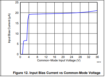
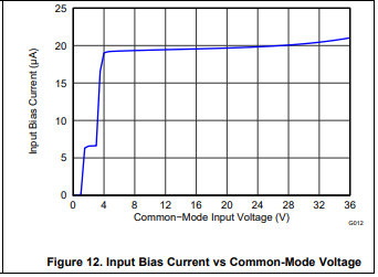
    Thanks for considering to use Texas Instruments.  According to electrical characteristics table, the typical current you might expect at your inputs which will be drawn across your 10 ohm filter resistors is 10uA.  The builk of this current can likely be attributed to an internal VCM detection circuit that adjusts internal rails for various circuit stages when the common mode voltage exceeds the device supply voltage.  When the VCM exceeds VCC, this internal circuit pulls more current from the input pins as shown in figure 12 of the datasheet.  As for the impedance to the ADC, we do not specify that.  However, as it is a delta-sigma ADC, I expect a buffer stage near the front and therefore a high-impedance.  I will check with our design engineers and see if I can provide you with a value on Monday. 

  • Thank you very much Patrick,

    Looking forward to more details.

    Please note that I am also very interested in the suggested symmetry of the resisors as I would like not to ruin the CMMR.

    Sebastian

  • Hello Sebastian,

    The impedance should be around 139 kohm.  As for the matching of your resistors, the tighter the tolerance on your resistors, the better.

  • Thanks,

    How 139Kohm is related to 10uA bias current?

    If impedance is 139k shoudl not the bias current be much lower?

    Is there any chance to get a hint how the mismatch in resistor values would affect the accuracy ?

    Best Regards
    Sebastian

  • I mean

    Is there any chance to get a hint how the mismatch in resistor values would affect the CMRR ?

  • Hello Sebastion,

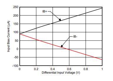
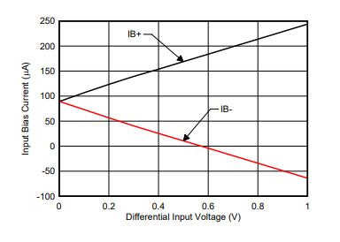
    In some of our newer devices we include IB vs Vsense plot such as in the example below (from INA240 datasheet).  However, older devices like the INA226 typically do not have them even though they have similar behavior.  In the second plot (from INA226 datasheet) you can see that once the common mode exceeds the supply voltage, the input bias current remains relatively unchanged.  This bump in bias comes from some circuitry that taps off from the bus to supply internal stages of the device.  This circuitry and what lies downstream can be equated to a current sink that is at some lower potential than your IN+ and IN-, the 139kohm corresponds to the impedance between the inputs and this sink.

    As for the error from mismatch, the resistor mismatch creates an offset that can increase the differential potential the ADC sees. In a simple case, we assume you have 1% resistors with the IN+ being 10.1ohm and the IN- being 9.9ohm. As vsense increases, IB+ rises and and IB- falls. If IB+=11uA and IB-=9uA. Then you will get an additional offset from these resistors equal to (10.1ohm*11uA)-(9.9ohm*9uA)=22uV. The error from this would then be 22uV/Vsense*100.

  • Thanks, this is very good information.

    Still need to nail some details to make sure I understand the issues.

    When calculating the effect of 10 R resistors ( assuming they ideal) is the difference between Ib+ and IB- main source of error?

    Are these resistors affecting differntial signals at all?

    Is there a way to estimate max difference between IB+ and IB - just looking at graph 12 (for INA226) ? I would like to estimate max error I can expect.

    The common voltage would be max 3.3V.

    Sebastian

  • Hello Sebastian,

    Yes, for ideal filter resistors the input bias difference would be the main source of error.

    The resistors are affecting the differential signal seen by the amplifier. The 22uV in my example above corresponds to a 22uV increase in the measured shunt voltage.

    As for the difference between IB+ and IB- you could take the 3.3 V point on the graph 12, roughly 7uA. Divide this by two to get 3.5uA for both IB+ and IB- when vsense is zero. Then as the common mode is the average of IN+ and IN-, half of your vsense differential should be seen between IN+ and the previously mentioned sink. With a resistance of 139k, the IB+ current should increase by (Vsense/2)/139K, while the IB- should decrease by the equivalent amount.

  • Thank you very much Patrick.

    Am I understanding it correctly, that ( assuming I discard the error's component due to Vsense)  at 3.3V I do have only +-3.5uA bias currents  not +-10 uA which I was assuming from the INA226  electrical parameters? This would be great.

    Sebastian

  • Hello Sebastian,

    Yes at common mode voltage different than the table's of 12V you will see a different input bias current.  In the case of a 3.3V common mode it will be around 3.5uA.  When I measured on my board I got about 2.5uA.  With respect to that, there was a detail that was overlooked before and I have since found that the impedance between an IN pin and the sink is closer to 6.25kohm.  If you are interested, I am attaching excel document in which I measured Ib with respect to Vsense.

    /cfs-file/__key/communityserver-discussions-components-files/14/INA226_5F00_inputBiasCurrents.xlsx