- Ask a related questionWhat is a related question?A related question is a question created from another question. When the related question is created, it will be automatically linked to the original question.
Hi Folks,
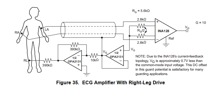
in the following, I will refer to the and the Figure 35 and Figure 36.
Most of the time when I use solid plane on the 2 layer PCB, I connect them to power supply GND. Similar to the Figure 36, where GND is used as IC's REF input and as I understand, the cooper plane under the chip is also connected to it.
But somewhere I heard that instead of GND I should connect the plane to Vg potential (Figure 35), that is common mode potential of the input.
So I would like to know is it true or not? How can I choose the right net for the plane filling? Any advise would be welcomed.
Regards,
Toth, Norbert