This thread has been locked.

If you have a related question, please click the "Ask a related question" button in the top right corner. The newly created question will be automatically linked to this question.

OPA858DSGEVM: OPA858

Part Number: OPA858DSGEVM
Other Parts Discussed in Thread: OPA858

Hello there, 

First of all, I am going to describe how I use OPA858DSGEVM. I connected a photodiode into the IN+, an oscilloscope with the OUT and the IN- ground. Using another circuit with a light source, LED, to control photodiode and expect the oscilloscope would record the signal. Besides, I set up all the connectors, voltage bias, and switch. However, it can not work in this way. It seems that there is no current went into OPA858DSGEV. Do you have any ideas about where it did wrong? I 

Best regards,

David Lin

  • Hello David,

      The default configuration of the OPA858DSGEVM is not ideal for testing a transimpedance application. The input capacitance from the photodiode can cause instability in the amplifier; this is solved by adding a feedback capacitor. There is no slot on this EVM were you would be able to place a feedback capacitor. You would be able to use a current source, but not with a non-ideal source that includes a capacitance like a photodiode. Here are three different links explaining how to design transimpedance amplifier circuits. The first link is quick video explaining choosing Cf and Rf depending on your desired bandwidth: link. The second link explains in depth for transimpedance designs with High-Speed Amplifiers: link. The third is an attached file which is a planetanalog article written by Michael Steffes that explains how to apply decompensated VFA's to photodiode transimpedance applications at the end of page 8.

    EDIT: The EVM has been tested in transimpedance configurations by stacking the feedback capacitor on top of the feedback resistor 

    Thank you,

    Sima 

    0042.Applying High Speed DeCompensated VFAs July1_2019.pdf

  • Hi, David, thanks for your reply. However, we have tried to connect a RF signal generator into J2.

    We have never think about to connect a photodiode instead of signal generator.

    In EVM datasheet, they said to use signal generator. Is it right to connect a photodiode directly?

    Please help solve this problem ASAP.

    Regards,

    Ki-Chang Lee

    P.S. In your case of connecting a photodiode to EVM, how do you get varying signals in ouput?

    Did you put any flickering light in front of the photodiode? I do not understand how to get amplified output waveform.

    Please reply me with detailed info.   

  • Hi Sima,

    Thanks for your reply. I think I know why the photodiode is not compatible with this EVM to work. Then, what if I use a voltage square source connects to the EVM input, will this work normally? I tried in this way, however, it showed nothing on the output oscilloscope. I might be wrong with something else about the circuit system. Do you have any ideas about this? 

    Thank you,

    David

  • Hi Ki-Chang,

    I think it is not right to connect a photodiode directly, it won't work. 

    Besides, I used another LED source, which connect to the function generator, to blink to control the photodiode. Then, the output supposes to be a waveform based on the LED source. I hope this could help you.

    Best,

    David 

  • Hello David, 

       It should work with a voltage square source as your input. However, you need to be careful with the OPA858 common-mode input range and output range which will depend on your voltage supply. I have attached a snippet from the datasheet on the allowed range when using a +5V or +3.3V single voltage supply. Would you be able to show me a scope shot of your input or be able to tell me the characteristics of your input signal (Amp/Freq). Also, if you missed it in my last edited reply, the OPA858DSGEVM worked in a transimpedance configuration by stacking the appropriate feedback capacitor onto the feedback resistor. 

    Thank you,

    Sima

  • Hello, Sima Jalaleddin and David,

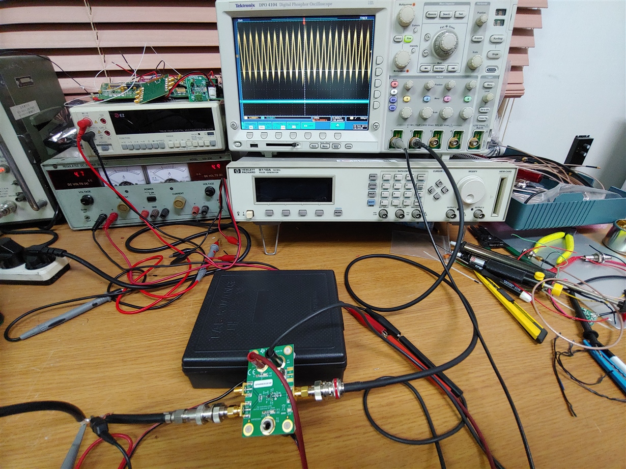
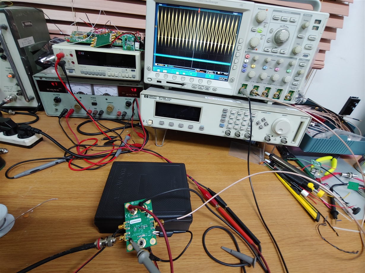
    As I promissed you the other day, I am sending our OA858 test setup phot with oscilloscope and EVM.

    We provided RF signal generator carrier signal (ranging 1Mhz to 30Mhz) about 3mV onto J2 of the OPAEVM.

    The yellow waveform shown is input, while no outputon output terminal wihich is blue baseline.

    It is evident that the EVM is out of order most probablly the OPA chip is bad.

    The EVM was purchased through Mouser company a couple of weeks ago, and when we asked for return shipping,

    they said that by contract between Mouser and TI, we have to return the degective item directly to to Tecas Instrument.

    Would you process our return and replacement shipping, if there isn't any other possible trouble-shooting support?

    We have to design a LiDAR receiving unit prototype using OPA8658 soon. The project is a governmental0-supoorted 

    development project supported by Hoseo University Industry-Academia Cooperation Founation.

    https://e2e.ti.com:443/Ki-Chang Lee

    Reserach Fellow  

  • Hello, Sima Jalaleddin and David,

    As I promissed you the other day, I am sending our OA858 test setup phot with oscilloscope and EVM.

    We provided RF signal generator carrier signal (ranging 1Mhz to 30Mhz) about 3mV onto J2 of the OPAEVM.

    The yellow waveform shown is input, while no outputon output terminal wihich is blue baseline.

    It is evident that the EVM is out of order most probablly the OPA chip is bad.

    The EVM was purchased through Mouser company a couple of weeks ago, and when we asked for return shipping,

    they said that by contract between Mouser and TI, we have to return the degective item directly to to Tecas Instrument.

    Would you process our return and replacement shipping, if there isn't any other possible trouble-shooting support?

    We have to design a LiDAR receiving unit prototype using OPA8658 soon. The project is a governmental0-supoorted 

    development project supported by Hoseo University Industry-Academia Cooperation Founation.

    Reserach Fellow  
    Ki-Chang Lee

  • Hello Ki-Chang,

       The file was not attached to the post. Would you be able to insert the file again using the insert file icon or insert media icon? Also, please keep all replies on one thread. 

    Thank you,

    Sima 

  • Hello Ki-Chang,

       I replied at your older thread: https://e2e.ti.com/support/amplifiers/f/14/t/851655

    Thank you,

    Sima