A related question is a question created from another question. When the related question is created, it will be automatically linked to the original question.
If you have a related question, please click the "Ask a related question" button in the top right corner. The newly created question will be automatically linked to this question.
TLC372: Some questions about TLC372 application circuit.
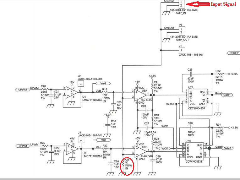
looks like R26 shall present a low impedance to the comparator input in order to make the input line more immune against EMI (capacitive stray coupling, etc.). Remember that TLC372 is a CMOS chip with very high input impedance.
R26 can also form a voltage divider in combination with a source resistance of input signal driver.
Or, R26 might be needed to convert a current input signal into a voltage signal.
There can be many reasons for R26.
What I don't like so much in the circuit is C26 and C30. Never put a cap directly at the output of a comparator. When going low a very high current pulse can be the consequence, possibly eroding the signal ground and causing ground bounce within the comparator chip. Even oscillation of the comparator can occur. Caps directly at the output of a comparator is a no go. If you want to filter the output signal of a comparator by the help of a cap, then always insert a suited current limiting resistor.
Another disadvantage of the circuit is the lack of an added hysteresis. This can result in heavy oscillations.
looks like R26 shall present a low impedance to the comparator input in order to make the input line more immune against EMI (capacitive stray coupling, etc.). Remember that TLC372 is a CMOS chip with very high input impedance.
R26 can also form a voltage divider in combination with a source resistance of input signal driver.
Or, R26 might be needed to convert a current input signal into a voltage signal.
There can be many reasons for R26.
What I don't like in the circuit is C26 and C30. Never put a cap directly at the output of a comparator. When going low a very high current pulse can be the consequence, possibly eroding the signal ground and causing ground bounce within the comparator chip. Even oscillation of the comparator can occur. Caps directly at the output of a comparator is a no go. If you want to filter the output signal of a comparator by the help of a cap, then always insert a suited current limiting resistor.
Another disadvantage of the circuit is the lack of an added hysteresis. This can result in heavy oscillations.
Kai
Dear Kai,
Thanks for your detailed answer.
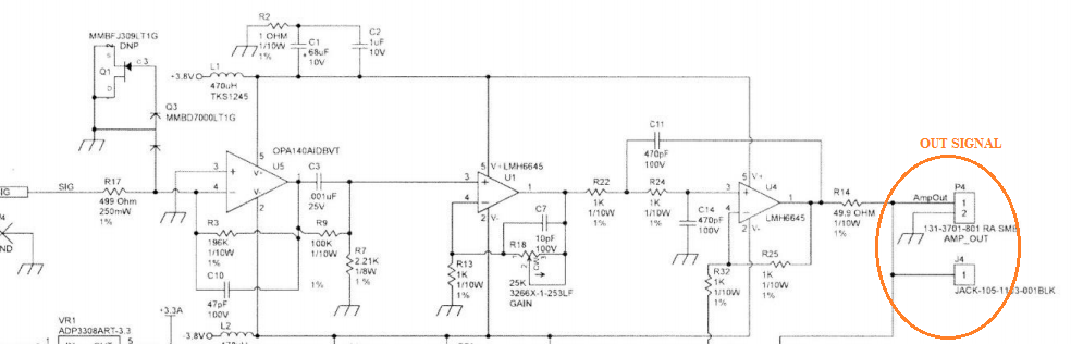
Here is the circuit diagram of comparator opamp input signal.
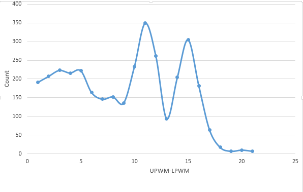
And, here is a statistical chart of signals with different amplitudes (desired results).
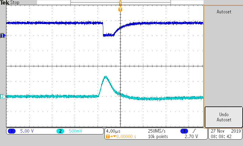
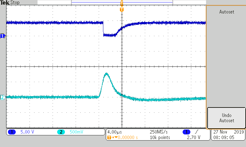
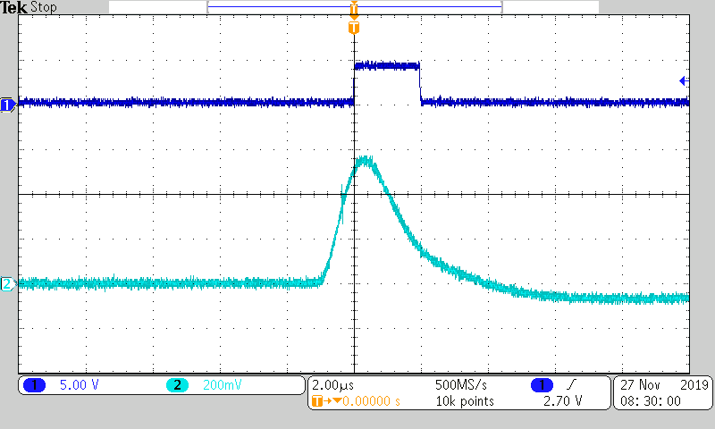
And this is the actual measured results.
From picture 3:
1.Can see that it can not distinguish the two peaks, as shown in Figure 2
2. The vertical axis is much higher than the desired value in Figure 2.
How to increase the ability to distinguish pulse amplitude, I mean the resolution of opam comparator?
what do the two statistical charts mean in detail? What have they to do with the comparator circuit? Or by other words: Where do you see from that the comparator circuit is not able to distinguish pulse amplitudes good enough?
what do the two statistical charts mean in detail? What have they to do with the comparator circuit? Or by other words: Where do you see from that the comparator circuit is not able to distinguish pulse amplitudes good enough?
Kai
Dear Kai,
Two statistical graphs with horizontal axis representing pulse amplitude.
And the vertical axis represents the number of pulses.
As in the first chart, it can be seen that pulses with amplitudes are clearly expressed according to the characteristics of the signal source. And the second chart seems to have overlapped.
Looking at the waveforms, and not the statistical charts, the only potential issue that I see is the loading on the output (cap load that Kai mentioned previously). This is causing the rising edge to be very slow. Is it possible that is causing your system to not capture pulses that are close in time? You are using a relatively fast response comparator but then you are slew rate limiting the outputs by connecting a cap load directly on the output. At the least, I would re-run your experiments with the cap loads removed.