This thread has been locked.

If you have a related question, please click the "Ask a related question" button in the top right corner. The newly created question will be automatically linked to this question.

Millivolt range AC to DC OP ?

Other Parts Discussed in Thread: TL052, TINA-TI, OPA27, OPA4227, OPA4228

Hello.

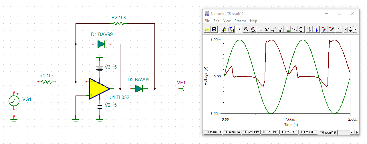
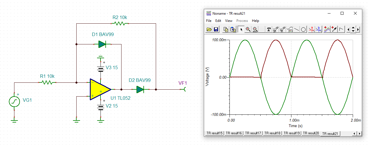
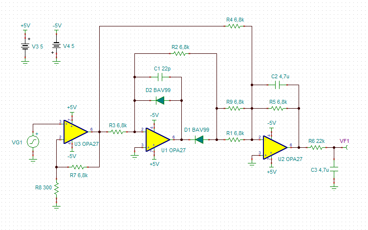
I am looking for an OP / Precision rectifier which to operate with input voltage of a 1 mV AC ( in the range of 1 to 1kH ) ( if not available such - then the closest as the best ) to about 100 mV, and output suitable for detecting from some 16+ bit ADC. ( probably in the range 500 mV - 5V or alike ).

The input as well can provide very tiny amount of current ( like a few up to tens of nA ).


Any information and guidances is helpful. :)

  • Hi Yordan,

    rectifying such a small signal is very tricky because the rectifier would need a very high gain to overcome the turn-on voltage of rectifying diode. For a 1mVs signal and a turn-on voltage of 700mV a gain of more than 700 would be needed.

    A much better approach is to put an amplifier in front of the rectifier providing a gain of let's say 100. This would shift the 1mVs...100mVs signal range to 100mVs...10Vs. This is no longer a problem for a good precision rectifier circuit.

    Another issue is the offset voltage of OPAmp. To keep the DC error small an OPAmp with an ultra low offset voltage should be taken for the pre-gain stage. Or you could use a pre-gain stage with a high pass filter, forming an AC amplifier. To keep the cap of the high pass filter small, the high pass filtering could be performed with a DC servo loop.

    Kai

  • I have attached some simulations to demonstrate the effect of too small an input signal amplitude:

    yordan.TSC

    Kai

  • Wow !  Thank You very much that You are spend this much efforts on this ( for me great ) issue!

    I understand now the tricky part, and I am ready to accept the issues with it if the circuits above fit my needs.

    So TL052 will do the job done ?
    The graphic about 10 mV looks great, but i do not understand what gain i will get with this circuit.

  • Hi Yordan,

    the TL052 is only an example for a rather fast OPAmp which nevertheless "terribly" fails when trying to rectify a very small input signal. I work very much with the TL052 (even today). That's the reason why I have used it in the simulation.

    The gain is 1. What speaks against the use of TL052 with a 10mVs signal is its rather large offset voltage. Please consider that the simulation is not showing the worst case of offset voltage.

    Run a TINA-TI simluation by yourself to find out the effect of the OPAmp's offset voltage on the result of rectification.

    Kai

  • emh.. so.. is there any practical circuit which fits close to my needs ?

  • Hi Yordan,

    it depends...

    ...on available supply voltage(s),

    ...on acceptable current consumption,

    ...on desired precision,

    ...on costs,

    ...on whether you need half-wave rectification or double-wave rectification,

    ...on specifications of signal source,

    ...on specifications of load to be driven,

    ...on whether you want to build an AC amplifier or DC amplifier,

    ... and and and.

    Kai

  • These things can varry in so-so wide ranges.

    - I can build any kind of voltage required ( except the super precise ones )

    - I do not care for the consumption.

    - The desired precision of 10-20% is ok.

    - Cost - something below 10$ per chip would be awesome.

    - The signal source is impulse almost like sinusoidal signal which can change it's frequency ( i am regulating it ) in the range 10 hz to 4 khz. but I can decrease it below 4kHz if i need to.

    - The load will be the inputs of some high precision ADC which will interfacing some ESP32 or alike. I just wanna measure with so-so precision the voltage in sub 100 mV range with ESP32.

  • I've made this simulation and it looks promising, anyway I am not sure if I am on the right road.

    TL072 milivoltmeter.TSC

  • Hi Yordan,

    you could do it this way:

    Eventually, an additional buffer is needed at the output.

    yordan_opa27.TSC

    Kai

  • Hey Kai !
    Thank You tons about your help on this problem.
    I would like to ask  ( since i am not understanding completely ):

    - what's the goods on this circuit, and how it is better than the last one ?

  • Hi Yordan,

    the OPA27 offers much lower DC errors, provided the feedback resistances are sufficiently low. So, there's no AC coupling necessary.

    Kai

  • Owww.. I see..

    So. I will stay with OPA27 and this circuit then. Anyway since I have to build this for 16 inputs which to acquire data simultaneously, i wonder if there is some maybe quad amplifier which will meet this requirements and fit in your circuit ( just to make the PCB smaller as possible ).

    Thank You again for helping kindly so far.

  • Update : Found that OPA4227N (quad OPA027) is the replacement of the new generation, and the circuit with it went pretty well looking, but the simulation with it show strangely low output (just by replacing yours with it)
    As well I have OPA4228N as an option .. if it is better.

    as well - these capacitor C2 and C3 - they are not polar or polar ? and the resistors R1 and R9 - why are in parallel ?

    Thank You again for spending time on this !

  • Hi Yordan,

    I ran a simulation and can say that the OPA4227 will also work very well. But decrease a bit the gain by increasing R8 to 330R. The error is under 1% for input signals between 1ms to 100ms then.

    C2 and C3 are non-polar. A ceramic high cap should do. R1 and R9 are in parallel because the parallel resistance should be half of R4.

    Kai

  • Hi Yordan,

    does it work for you?

    Kai

  • Hey Kai !

    I haven't tested yet.
    Still drawing the board, since it containing about 40 IC's.. , and was scared that i will not build something working. That's why I am looking for something which is working goodly. :)
    And I am thankful that You have spending this time helping me out ! :)
    Btw - between OPA4227 and OPA4228 - which one to chose ?

  • Hi Yordan,

    the OPA4228 is a decompensated version of the OPA4227 and is very much faster than the OPA4227. But the OPA4228 can only be used with a gain greater than 5. Theoretically, you could replace the first OPAmp in the circuit (U3 in my last simulation) by the OPA4228, because this OPAmp runs at a gain greater than 5. But I wouldn't do that. The OPA4227 should be fast enough. If you would go for much higher input signal frequencies than 1kHz, then you could take the OPA4228 for U3.

    Kai

  • Hey Kai !

    Oh. I see.. So, I am going for OPA4227 then.

    Wonder if I put an analog multiplexer like 74HC4067 on the input and multiplex signals from a few sources - will this cause a big trouble ?

    My idea is to multiplex the input to the ground while the input of the signal to be common for all sources and connected to the input of the amplifier.

    The ON resistance of this analog multiplexer says that is about 70 Ohms..


    (cant find Tina model of this multiplexer :| )

  • Hi Yordan,

    I haven't understood this sentence:

    "My idea is to multiplex the input to the ground while the input of the signal to be common for all sources and connected to the input of the amplifier."

    Kai

  • Hey Kai !
    Well.. I have 6 input signals, and I would like to select between them with multiplexer like 74HC4067 attached the output pin to the input of the amplifier.