This thread has been locked.

If you have a related question, please click the "Ask a related question" button in the top right corner. The newly created question will be automatically linked to this question.

MEMS Microphone Amplifier design

Other Parts Discussed in Thread: OPA1671

Dear Team,

I will be designing a MEMS Microphone Preamplifier for one of my project. Microphone from Knowles will be used (Please find the attached schematic).

 Analog_Kaskade_spv1840lr5h-b-revd.pdfThey have given a reference schematic in that O/P of the Microphone is connected to DC blocking capacitor.

May I know how to select the capacitor, its vale and voltage rating?

also please suggest some opamp from ti for this application

Regards

Hari

  • Hi Hari,

    the capacitor is needed to couple the different DC voltages coming from the left side and the right side to each other. At the same time the cap in connection with Rs + Zout forms a high pass filter with a corner frequency (-3dB) of 1 / 2 / pi / (R x C). What frequency response do you wish?

    The cap must withstand the supply voltage of OPAmp and microphone and should have a bit headroom. What supply voltages do you use?

    The OPAmp should be a low noise version.

    Kai

  • Hello Hari,

    Kai has provided good guidance regarding the determination of the input dc blocking capacitor value. Since the microphone element is low voltage and it appears  you will be using a low voltage op amp (< or = 5 V) as well the capacitor voltage rating doesn't need to be high. A common low DC working voltage capacitor rating is 10 V and that should be sufficient for this application. If you decide to use a high voltage op amp the capacitor voltage can be increased at the expense of larger size.

    I suggest you have a look at the OPA1671. It is a low noise, low voltage audio op amp. Its specifications should be a good match for this microphone amplifier application. You can find the datasheet here:

    http://www.ti.com/lit/ds/symlink/opa1671.pdf

    Let us know if you have any questions.

    Regards, Thomas

    Precision Amplifiers Applications Engineering

  • Hi kai,

    Please find the bloack diagram of my system.

    I have a few queries regarding it. Please see below.

    Please see the system Details below

    Both the microphone and comparator are working at 1.8V.

    The intention of this circuit is when the microphone detects any voice activity comparator will trigger and wake up the DSP

    According to my understanding in the idle state, the O/P of the Microphone is 1.1V and when any voice activity comes this will go above 1.1V and come back to 1.1V when there is no voice activity. (Please correct me if I am wrong).

    1)      May I know how we can calculate how much it can go above 1.1V when it detects any voice activity

    2)      Is there any problem in connecting the Microphone O/P directly to the comparator, without removing the DC 1.1V. I think it is not a problem if I set the comparator threshold value higher than 1.1V(Please let me know your comments)

    Regards

    Hari

  • Hi Hari,

    is only human voice hitting the microphone or any other noise as well? In the latter case it can make sense to insert a band pass filter to separate the voice frequencies from the noise.

    Also, it can make sense to insert a delay or low pass filter, so that brief glitches will not be able trigger the voice detector.

    Can you tell a bit more about your application?

    Kai

  • Hi Kai,

    This is Acoustic activity Detection. Sound above 60dBSPL should trigger the comparator.

    I have converted Microphone sensitivity to a voltage value. Please find my attached calculation sheet.

    The minimum value coming is 1.100251487V and the maximum value obtained is 1.100501782V. Thsese values are obtained by adding 1.1V DC of Microphone to its sensitivity which is converted to voltage(Please see the excel file)

    The above values are obtained at 60dBSPL. My comparator should trigger for any acoustic activity greater than 60dBSPL.

    These values make comparator reference voltage selection difficult. My idea is to block the DC (1.1V) and amplify the remaining voltage which is obtained at the time of Acoustic detection.

    In the excel sheet for maximum sensitivity, its values are 0.501781907mv. I am planning to amplify this voltage and give it to one input of the comparator. May I know your thoughts about this?

    I am planning to provide a gain of 3000 so that for maximum sensitivity the O/P voltage of the amplifier will be 1.5V and for minimum sensitivity, my amplifier O/P will be .75V. This will make my comparator Reference voltage selection easy.

    May I know Is it possible to obtain a gain of 3000 using single-stage Opamp or do I need to cascade stages.

    regards

    Hari

    Calculations.xlsx

  • Hello Hari,

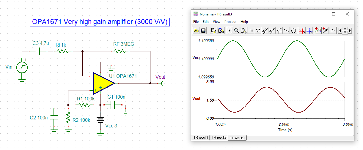
    A single op amp may be used for a very high gain amplifier, but that gain may come at the expense of distortion, bandwidth, noise, etc. I mentioned the OPA1671 previously and it will be used in a simple capacitor coupled inverting amplifier having a gain of -3000 V/V. The results from an ac simulation are shown here:

    The gain is 69.5 dB (3000 V/V) in the pass-band, with a 33.7 Hz lower cutoff from the 4.7 uF coupling capacitor and 1 k input resistor. The upper high frequency cutoff of 5.2 kHz is due to the normal OPA1671 open-loop gain (Aol) roll-off with frequency.

    A good thing about the RC coupled input is the op amp voltage offset is only multiplied by 1x. Therefore, the OPA1671 output referred voltage offset contribution is very low at the output.

    Regards, Thomas

    Precision Amplifiers Applications Engineering

    OPA1671_Very_high Gain_01.TSC

  • Hi Thomas,

    Thank you very much.

    My microphone has 1.1V DC output.at 60dBSPL the peak value coming is 0.501781907mv.Please see the calculation excel

    Once the DC(1.1V) is blocked I will have only 0.501781907mv.(Please tell me my understanding is correct or not)

    The offset voltage of OPA1671 is 1.6mv which is greater than my I/P voltage.

    May I know can I use this op-amp for amplifying my signal.

    Regards

    Hari

    0.501781907
  • Hi Hari,

    according to this link

    94dB (SPL) is about 1Pa. The sensitivity of your micro is -38dBV/Pa, which means 12.6mV/Pa. 60dB (SPL) means that your signal is 34dB smaller, or by other words, 1/50 of 12.6mV, which is 0.25mV. All these voltages are RMS values. So, the amplitude of your signal is 0.25mV x SQRT(2) = 0.35mV.

    As the following simulation shows, the circuit Thomas developed for you will properly work:

    Even with added offset voltages the circuit will work, because the offset voltage is NOT amplified by the high gain. You can easily understand this when keeping in mind that for DC the impedance of C3 becomes infinite. So, the DCgain will be

    DCgain = (3M + (1k + infinite)) / (1k + infinite) = (3M + infinite) / infinite = infinite / infinite = 1

    hari_opa1671.TSC

    Kai

  • Hi Kai,

    Thank you  very much...

    May I know the role of V1,R1,R2,C2...

    Can we Implement Non Inverting configuration for the Same

    Regards

    Hari

  • Hi Hari,

    V1 only simulates the effect of offset voltage of OPA1671. Of course, there's no need to mount it in the ready built circuit :-)

    R1 and R2 generate a bias voltage at midsupply to allow the output voltage of OPA1671 to swing in positive and negative direction. C2 filters out supply voltage noise and ripple and presents a low impedant path to signal ground for the +input of OPA1671 at higher frequencies. This stabilizes the OPAmp and decreases the noise contribution of OPAmp and voltage divider.

    C3 provides the discussed AC coupling and forms a high pass filter in connection with the output impedance of microphone and RI. To achieve low noise RI should be kept small. The drivability of micro sets the lower limit. Remember that the right side of RI sits at "virtual ground" or better said "virtual midsupply". Thomas has found a very good compromise here with RI=1k.

    RF sets the gain of this circuit and C1 finally decouples the supply voltage.

    Yes, a non-inverting scheme is possible but would need two more components. The only advantage of a non-inverting scheme is that you can furtherly decrease the OPAmp noise and resistor noise. But it has no effect on the noise the micro generates itself.

    Kai

  • Hi Kai,

    Thank you very much..

    Is it good option to connect an RMS to DC converter at the O/P of my Microphone.

    Regards

    Hari

  • Hi Hari,

    a RMS to DC converter might be too costly for your application I guess. Or do you need to know the exact RMS value of microphone signal?

    A simple but effective audio detector is discussed here:

    Kai

  • Hi Kai,

    I did the non inverting configuration and it is working fine.

    Please find the attached.

    NOn_INV.TSC

    Do I need to consider MIC O/P impedance during the design of Non-Inverting amp?

    We are planning to connect the O/P of this amplifier to a comparator.

    Do I need to use an LPF after the O/P of Amplifier(before connecting to Comparator I/P). The function of LPF is to do averaging.

    as per my knowledge, an LPF acts as an averaging circuit after it's cut off frequency.(Please correct me if I am wrong.

    Regards

    Hari

  • Hi Kai/Thomas,

    Thank you very much for your support.

    I implemented the non-iverting Amp using two stages two increase the Bandwidth.

    My fL is 52.54 and fH is 205K. If I can reduce the fL near to 20Hz it is well and good, but I failed.

    Please check the attached Schematic. Please let me know it is fine or not.

    G-50_60.TSC

    Regards

    hari

  • Hi Hari,

    why do you expand the bandwidth, if the only you want to detect is human voice?

    The circuit Thomas developed for you is pretty much perfect. Why would you want to change it?

    Kai

  • Hi Kai,

    My system should detect any Acoustic Activity above 69dB SPL.

    From the microphone datasheet what I understood is, it will work properly up to 10 Khz(please correct me If I am wrong)

    The circuit Thomas designed will work up to 5Khz(May I know I am correct).so I thought any I/P which comes above 5Khz at the MIC I/P

    cannot be processed by the circuit which Thomas designed.

    That is why I asked for more Bandwidth.

    I don't know my thinking process is correct or not.

    May I know your suggestions.

    Regards

    hari 

  • Hi Hari,

    see the typical frequency range of human voice:

    So, for detecting human voice there's no need to extend the bandwidth above 5kHz.

    Kai

  • Hi Kai,

    Thank you very much.

    Output of this amplifier will go to a comparator and comparator output will be connected to DSP.

    I have some Queries regarding this.

    1) Do I need to connect an LPF(passive) after amplifier output.My intention to connect LPF is to do averaging.

    Regards

    Hari

  • Hi Hari,

    have you seen the link above? I post it again:

    sound-au.com/project38.htm

    Kai

  • Hi Kai,

    I will study it and will contact you for any further clarifications.

    Thanks & Regards

    Hari

  • Hi Kai/Thomas,

    I started the prototype and it is working well.Thank you for your support.

    Could you please suggest some low cost alternate for OPA1671. Mine is a low cost system.

    The OP-AMP  supply in my system will be 1.8V.

    Regards

    Hari

  • Hello Hari,

    If your application goes into high volume manufacturing the price that the OPA1671 can be purchased in quantity will certainly be lower than the 1ku price listed on the web page. I suggest that you contact your local TI Technical Sales Representative (TSR). They should be able to provide you with more competitive, volume based pricing information.

    Regards, Thomas

  • Hi Thomas,

    Thank you very much.

    I implemented the non-inverting version of the circuit provided by you. In a general-purpose PCB

    We changed Rf value to 1M. Unfortunately, it is oscillating. All the node voltages are coming as expected

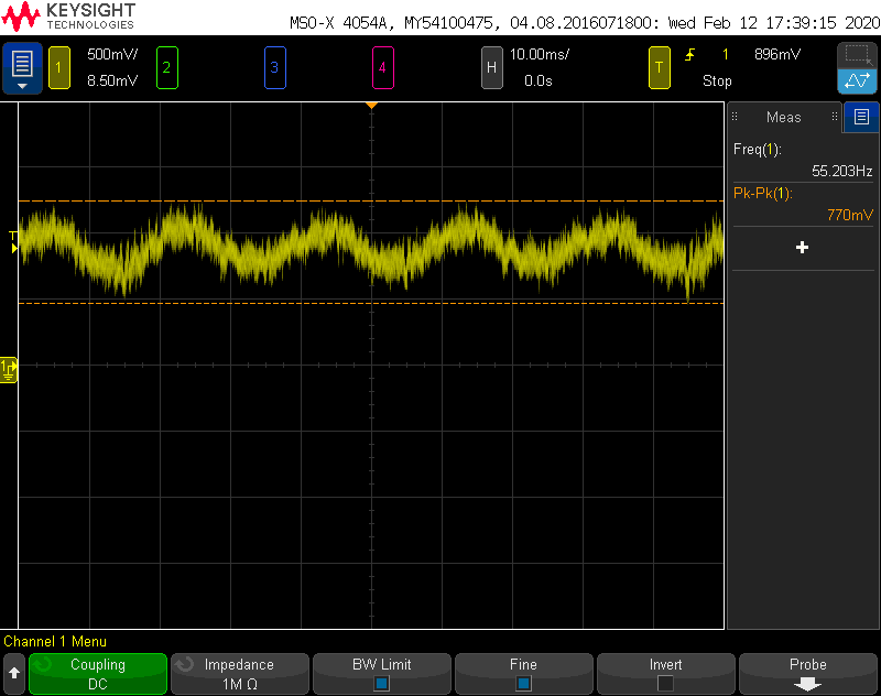
    Sending the Circuit diagram, output waveform, and Test Board PICs.

    Please tell me where I went wrong

    Regards

    Hari

    Non_Inv_1.8V_G=1000.TSC

  • Hello Hari,

    I suspect that the sine wave you are seeing at the high-gain OPA1671 MEMS amplifier output is not oscillation, but power line energy coupling into the circuit. I see that the frequency indicated on the DSO is 55 Hz, halfway between 50 Hz (Eu/Asia) and 60 Hz (Americas) line frequencies. I suspect that because the sine wave is noisy that the DSO is a little uncertain about the actual frequency.

    When a high gain amplifier is left out into the open the various wirings in the building, line cords and ac sources in close proximity to the circuit capacitively or magnetically couple 50/60 Hz signal into the exposed circuit board, or the dc wires providing power to the circuit. When testing such circuits in our lab we often place them inside a metal enclosure, and power them from batteries inside the enclosure. The input and output from the circuit goes to coaxial connectors such as BNC connectors so that shielded coaxial cables can be used to connect the input signal source and external load.

    You may find if you place the exposed on the lab bench and then lift the board away from the bench that the amplitude of the sine wave changes. That is an indicator that the amount of signal coupling is changing and verifies that it is originating from the room's ac circuits. 

    Regards, Thomas

    Precision Amplifiers Applications Engineering

  • Hi Thomas,

    Thank you very much.

    Your observations were correct.

    I lowered the gain and now it is working fine.'

    Regards

    Hari