A related question is a question created from another question. When the related question is created, it will be automatically linked to the original question.
If you have a related question, please click the "Ask a related question" button in the top right corner. The newly created question will be automatically linked to this question.
UAF42 has two different IC packages, namely UAF42AUE4 (SOIC-16 or U package) and P package (UAF42AP in PDIP-14). They are the same die, but pin 2 and pin 15 in UAF42AUE4 (SOIC-16) are NOT Connected or used.
In the Tina model UAF42E, where "E" refers to enhanced Tina model. I am not sure what you are asking. In Tina's model, UAF42AUE4 and UAF42E are identical. If UAF42AUE4 is used in schematic drawing, please make sure that you follow the pin description prescribed in the UAF42 datasheet.
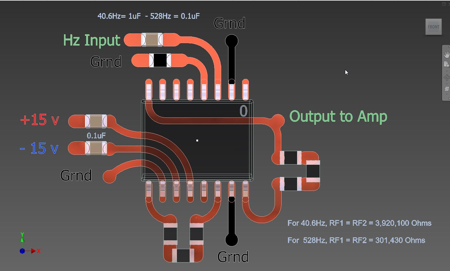
kai klaas69 has addressed the Pin Count of 16 for me thank you, as per the image below.
You must forgive me, but with our electronics technician severely ill in hospital, I am double checking everything just to be certain. I do not want to end up using the wrong components.
But you have kindly confirmed that I am using the right component thank you.
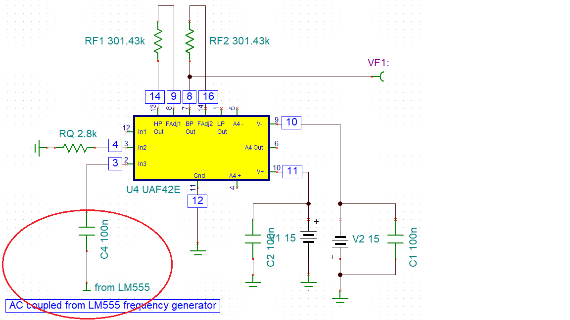
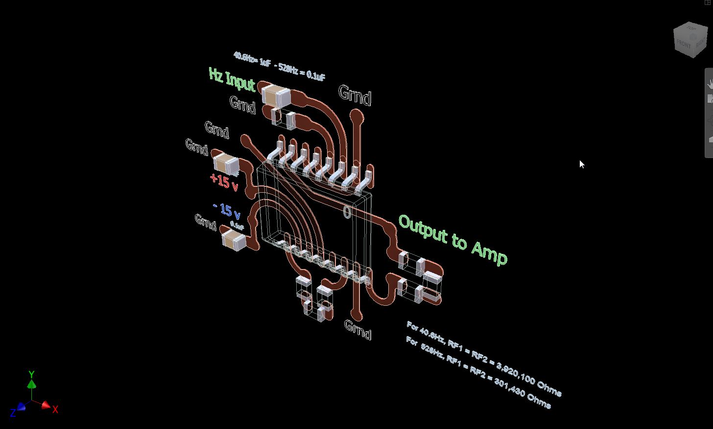
Per your schematic, the UAF42AUE4 (SOIC-16) pin out is good vs. UAF42 PDIP-14 package. However, you made 3 errors in how the coupling capacitors should be placed, see the red circles below. The power sources should be connected directly to ground, Not AC coupled to ground.
the most left cap wasn't so wrong, if Christopher wants to drive the input of UAF42 with a LM555 which is powered by an unipolar supply voltage. See also here:
Kai is correct, if the signal of VG1 comes from LM555 frequency generator, which the input signal is AC coupled to pin3 of UAF42AUE4, see the schematic drawing.
You may want to optimize the values of coupling capacitance accordingly. The impedance of coupling capacitor at VG1 is 1/(2*pi*f*C). For instance, if the input frequency is 528Hz and coupling capacitance is 0.1uf, the input impedance at pin3 (UAF42AUE4) is 1/(2*3.14*528Hz*0.1uf)=3016 Ohm. For 40.6Hz. the input impedance of the same coupling capacitor will be 39.2kOhm.
I am currently modelling this component and its connections as I write.
So that I am clear, are you advising that the two separate capacitor values between Pin3 of the UAF42 and the LM555m should be as follows: 40.6Hz = 39.2kOhm 528Hz = 3016 Ohm
I would be most grateful for your kind confirmation, please?
Also, would you be prepared for me to send you an image of the UAF42 complete with its immediate circuit, resistors and capacitors to kindly confirm that I have not further erred?
Enclosed are two simulation circuits for 40.6Hz and 528Hz. For 40.6Hz signal, I increased the coupling capacitor to 1uf in order to increase the output amplitude (+/-1.66Vpp). For 528Hz signal, I left 0.1uf as the coupling capacitor, see the simulation.
I removed both 0.1uF coupling capacitors from 15V power supply. For some reasons, the simulation is really slow when the coupling capacitors are added. You can add these coupling capacitors when you are doing final schematics.
As you can imagine, with helping over 100 cancer sufferers on the QT to fully self-heal, BigPharma is not best pleased with me. Even though I am having to keep my head down, I have the ability to help so many more. Sadly the public has been duped, as they have over so many things, into believing it is impossible to self-heal. That is why the industry is only second to the war industry in revenue generation. Thank you so much for your help, along with those others whom have so willingly assisted me thus far.
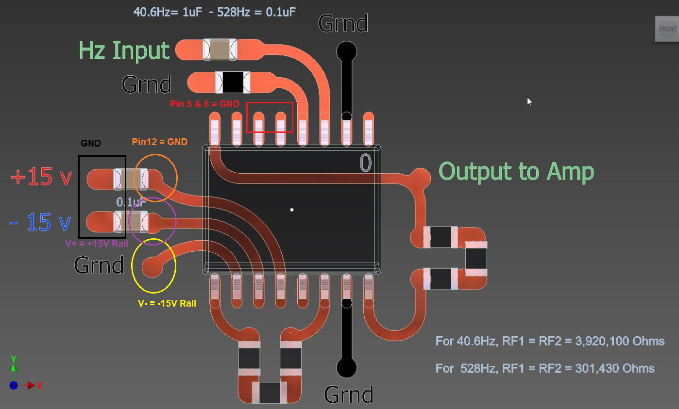
One more correction please, see the image. The power rail connections are at the circled location, and opposite side of capacitors will be connected to GND. for +15Vdc and -15Vdc.
It is not easy to sort out the components, not having a background in electronics.
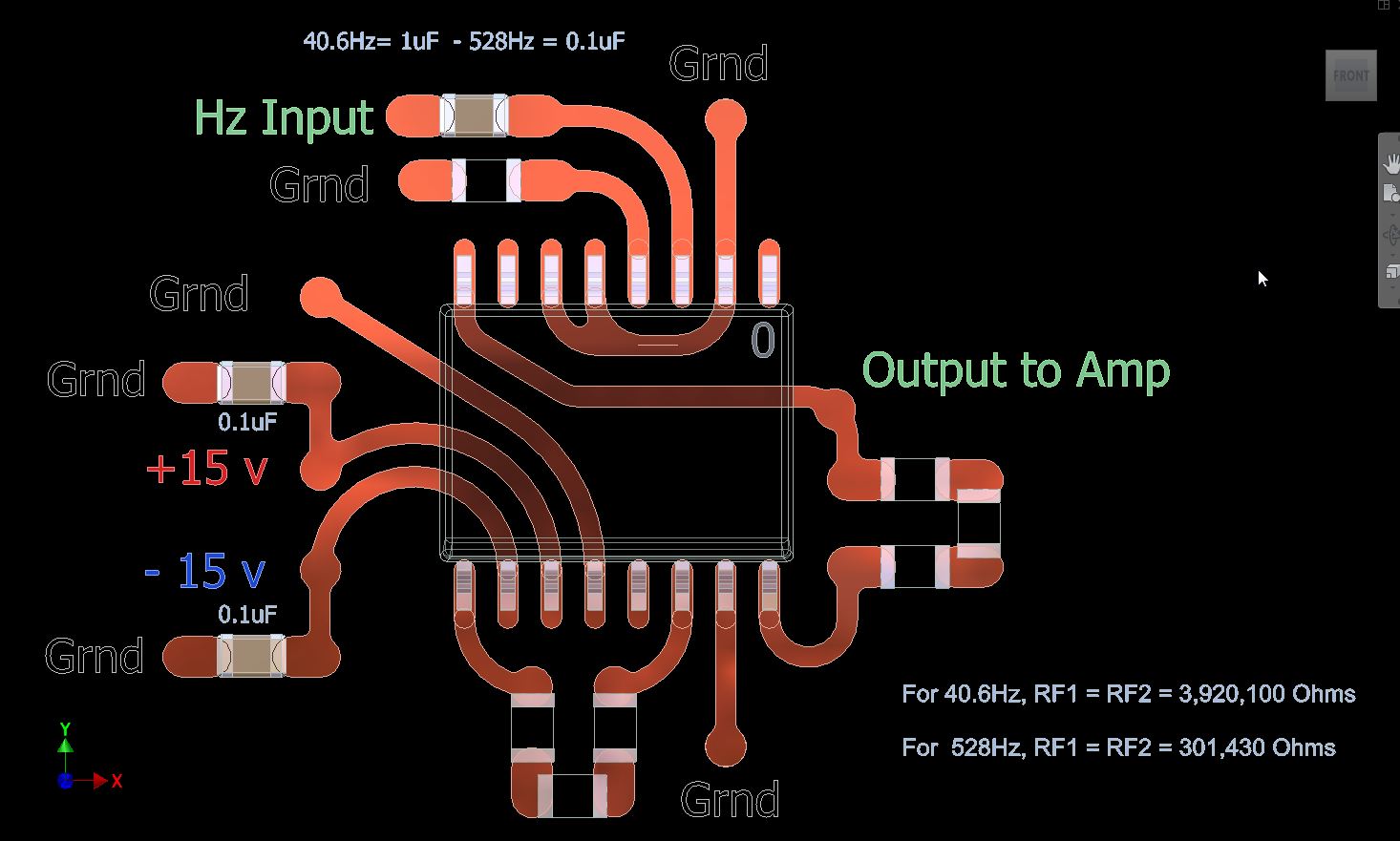
Someone asked why I did not stick to straight lines and 45 degree angles to which I replied:
"Our circuits are not simply about conveying electricity. Thay are about the trasmission of energy, and thus are structured in much the same way as 'Nature' structures living organisms."