This thread has been locked.
If you have a related question, please click the "Ask a related question" button in the top right corner. The newly created question will be automatically linked to this question.
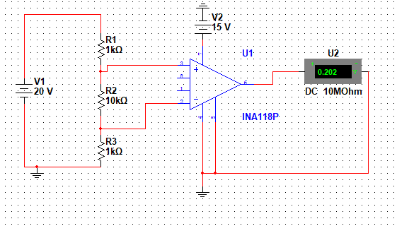
in this circuit voltage across R2 is 16.66, but why output voltage is zero? instead of saturating at VCC?
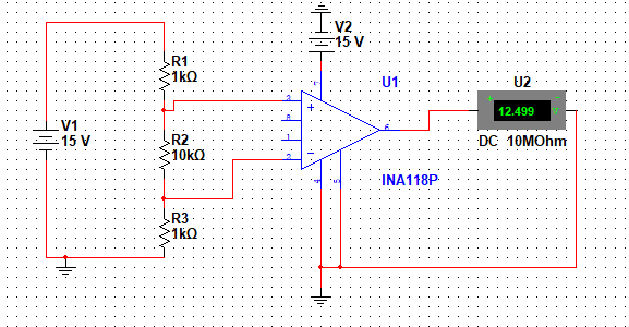
in this circuit voltage across R2 is 12.5, and this circuit works well
I'm simulating this circuit, and also i have made it practically, in both cases for input voltage ( voltage across R2) upto certain value this circuit works well, but as the input voltage across (Voltage acorss R2 ) reaches near VCC supply voltage , output voltage suddenly drop to zero from 13 voltage! please suggest how i can eliminate this problem, waiting for an early reply please.
in my circuit V1 voltage will vary from 0 to 24 volts, and i want that as voltage across R2 becomes greater than or equal to VCC voltage output saturate at VCC instead of suddenly dropping to zero from 13 volts.
Hi Amir,
Thank you for your post, I can help you.
As V1 varies from 0 to 24V, the voltage across R2 varies from 0 to 20V. The INA118 input voltage range is shown in the product datasheet on page 6:
So, in order to capture 0 to 20V, you need to power the INA118 with -1.1V to 21V.
Thank you for your reply.
but why output of INA118 or instrumentational amplifier drop to zero for input voltage near VCC?
Hi Amir,
Figure 25 of the datasheet shows a simplified representation of the INA118 and provides insight into its operation. Each input is protected by two FET transistors that provide a low series resistance under normal signal conditions, preserving excellent noise performance. When excessive voltage is applied, these transistors limit input current to approximately 1.5 to 5 mA.
When you operate the amplifier beyond its specifications, we cannot assure it's performance.
Please use the supplies I recommended if you want to capture 0 to 20V on the input.