Hi Team,
My customer is using THS4551 as a attenuate differential amplifier to driver SAR ADC. He has some questions below and need team's comment.
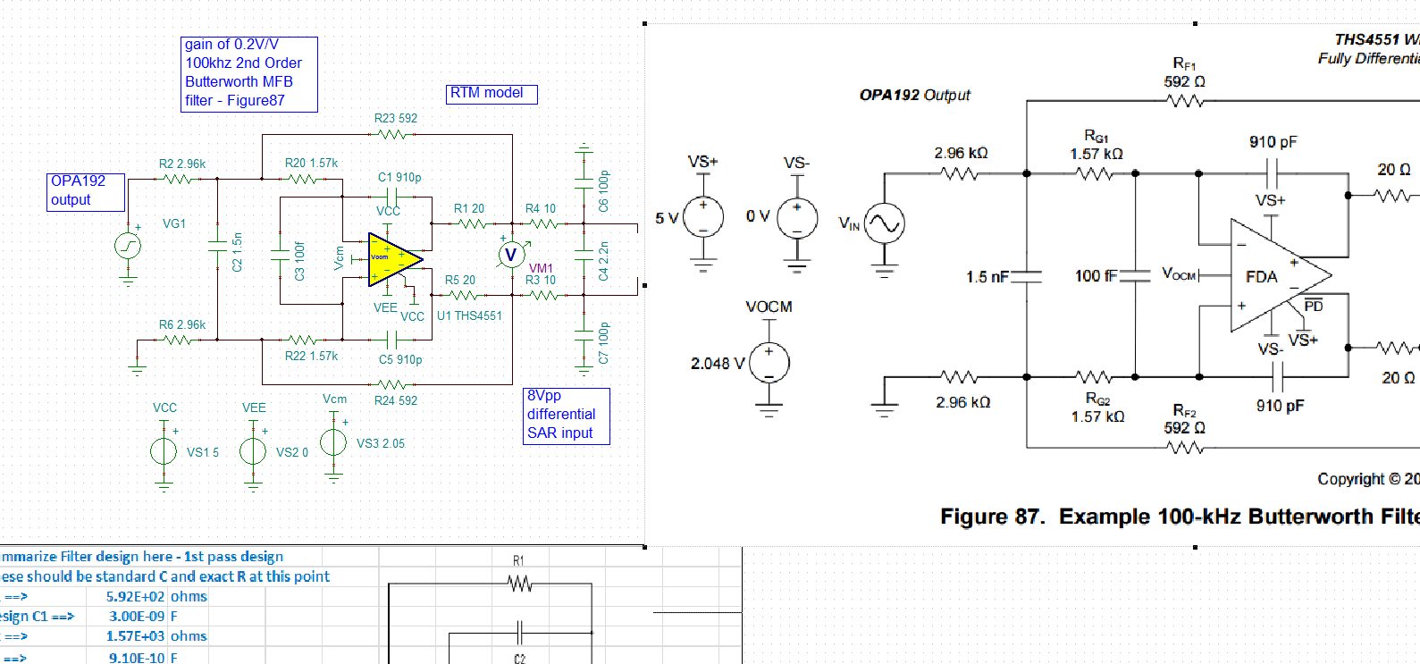
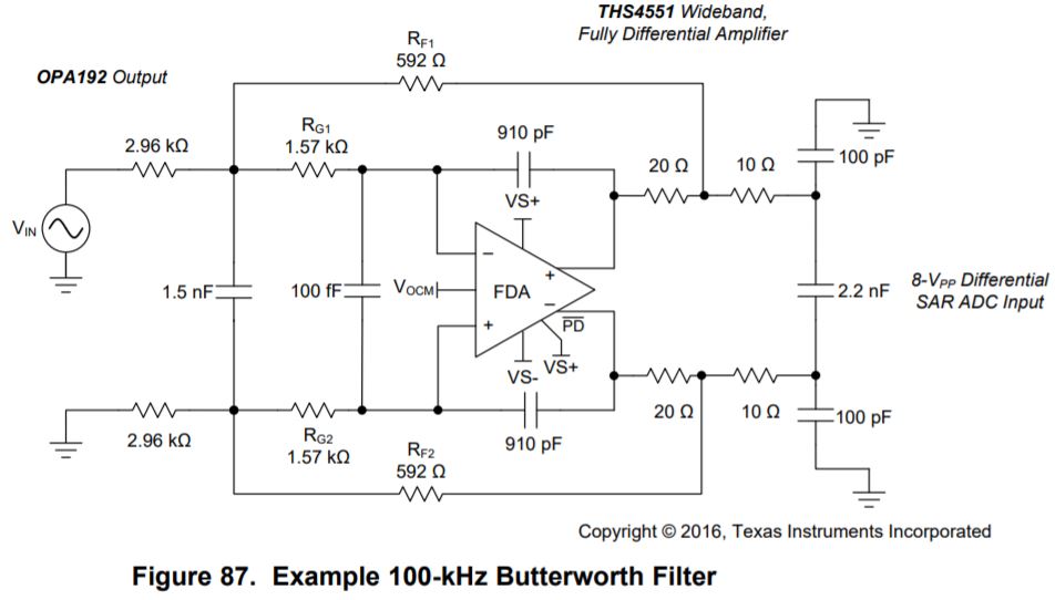
1. Below is a 100KHz filter, is there a document or speadsheet to guide customer how to calculate out the R, C value to achieve the bandwidth that customer want?
2. Below is customer's circuit, R&D would like to form a 25KHz butterworth filter, so is the R, C value of black line area correct? if not, please provide the recommendation.
3. Why need a differential and common mode filter in blue line area?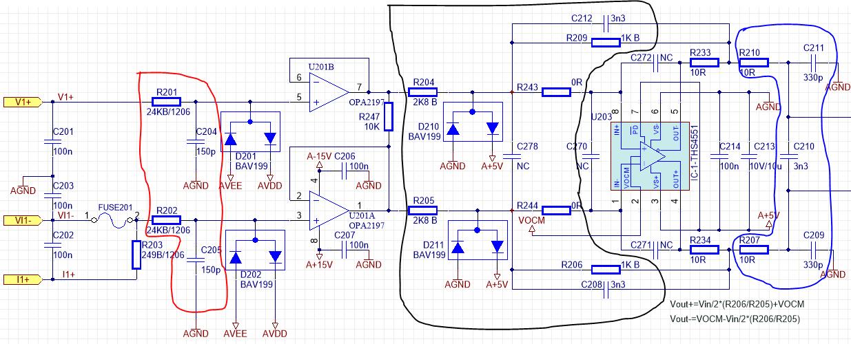
4. Can customer large the R, C value in blue line area to form a main filter(like to build a 25KHz filter)? If it is not recommended, why?
5. Customer try to change C210 from 3.3nF to 470nF, the -3dB should be at 1/(2*3.14*20*470n)=16.9KHz but his test result is about 8.9KHz, why? And he also found the total power consumption increase about 1W, does it make sense?
Thanks very much.
Vincent Chen