This thread has been locked.

If you have a related question, please click the "Ask a related question" button in the top right corner. The newly created question will be automatically linked to this question.

OPA564: How to simulate stability of Howland current source using opa564

Genius 3900 points
Part Number: OPA564
Other Parts Discussed in Thread: TINA-TI, THS4032

Hi there,

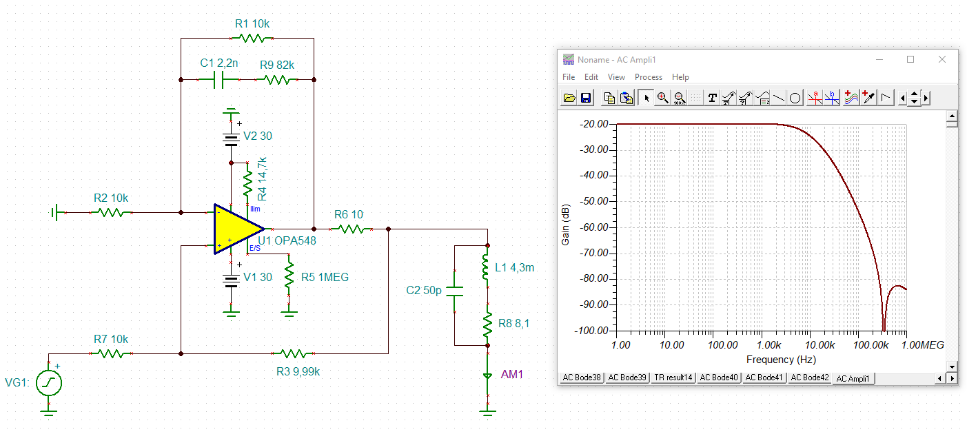
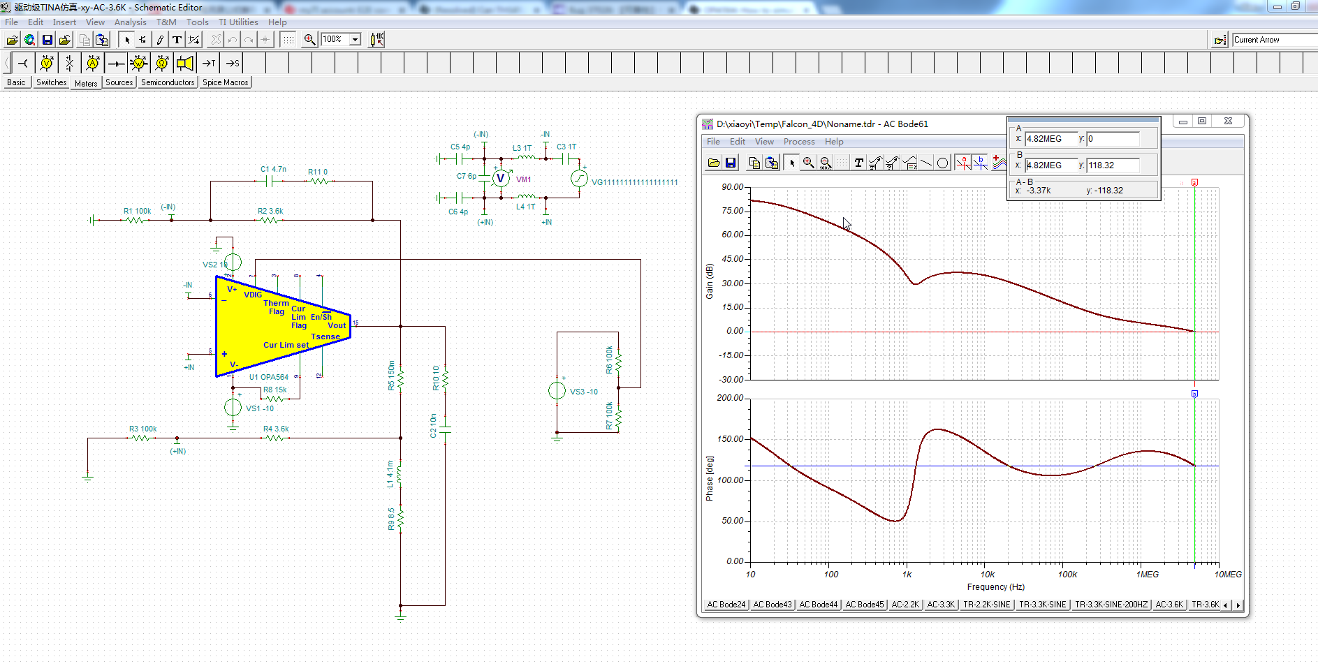
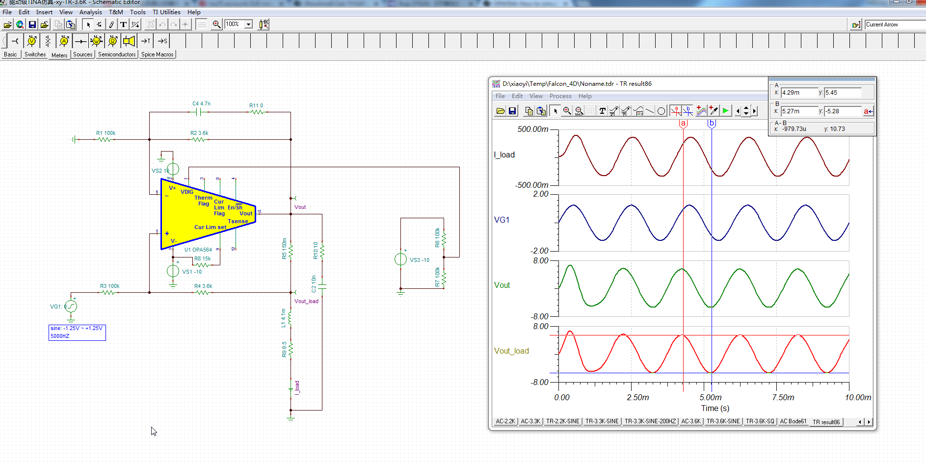
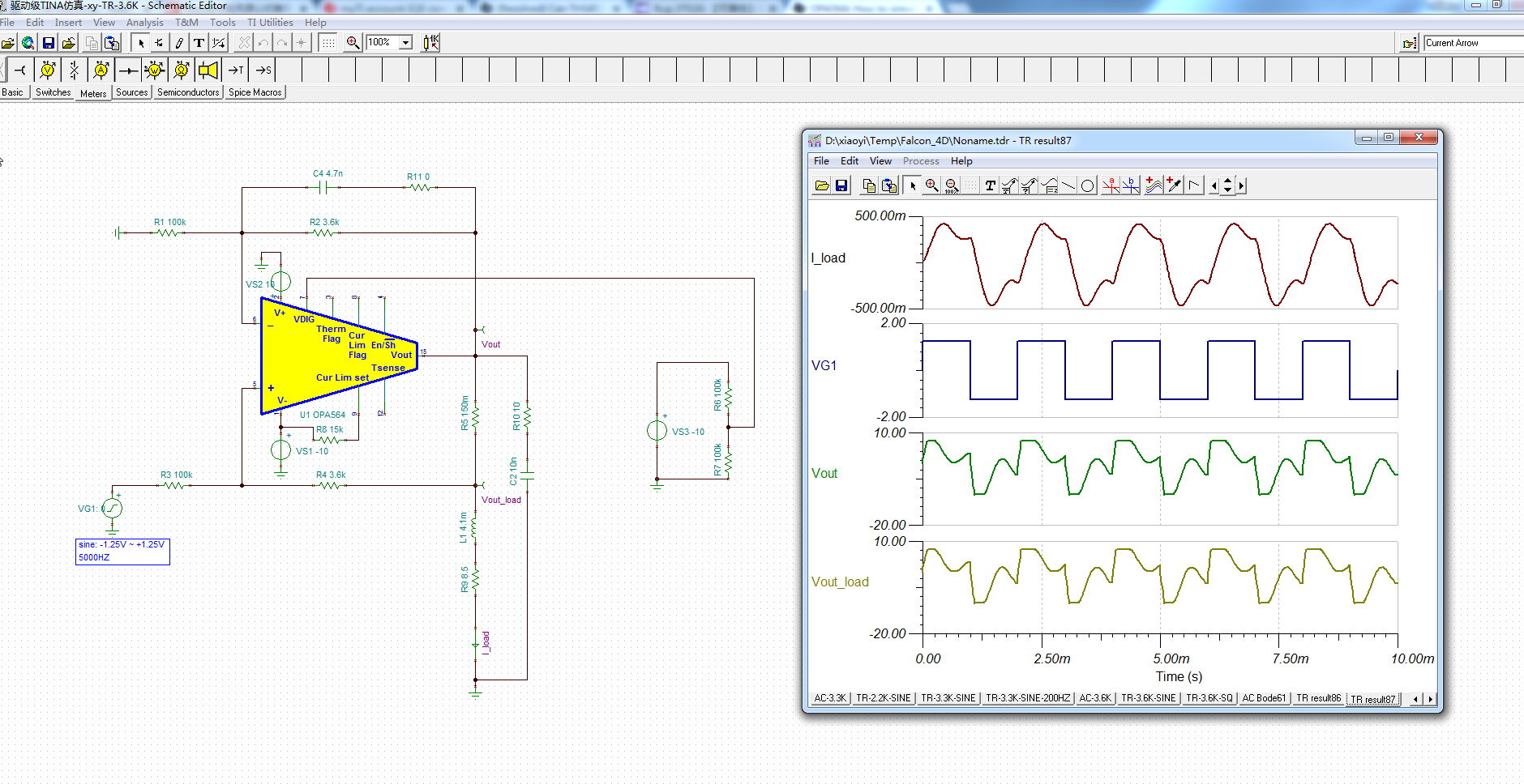
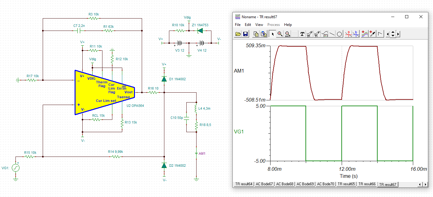
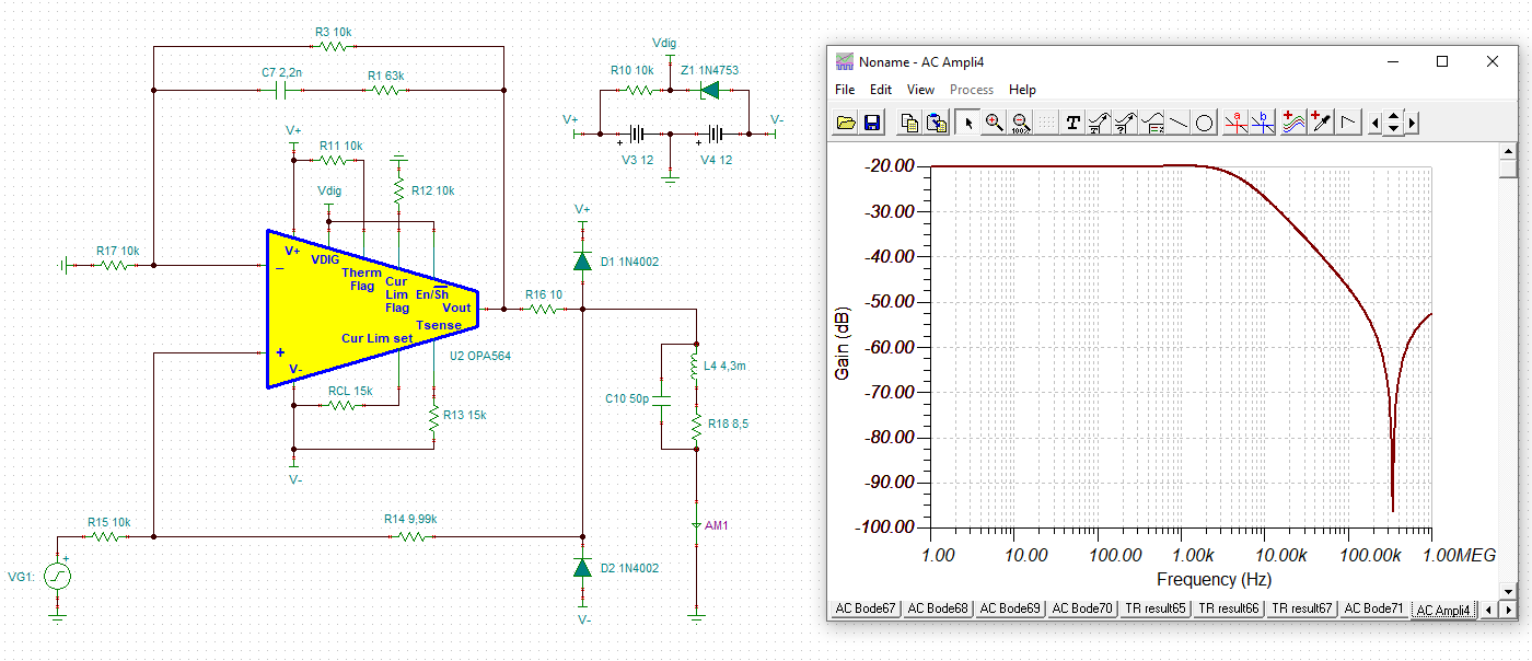
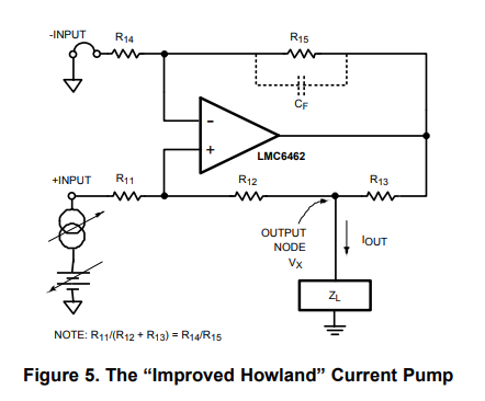
we will use two OPA564 configured as improved howland current source (SCH is refered to TI snoa474a Figure5. ), to drive two step motor coils (8.1ohm + 4.3mH), and we need to simulate the stability of this circuits.

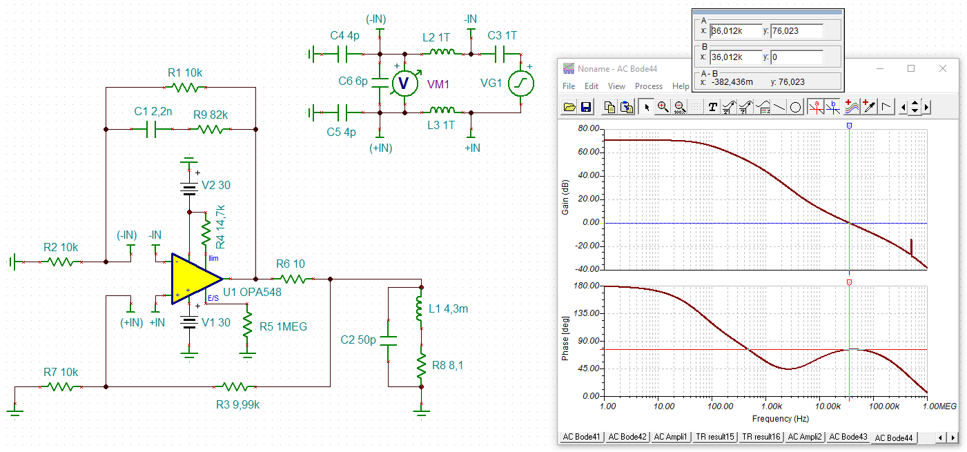
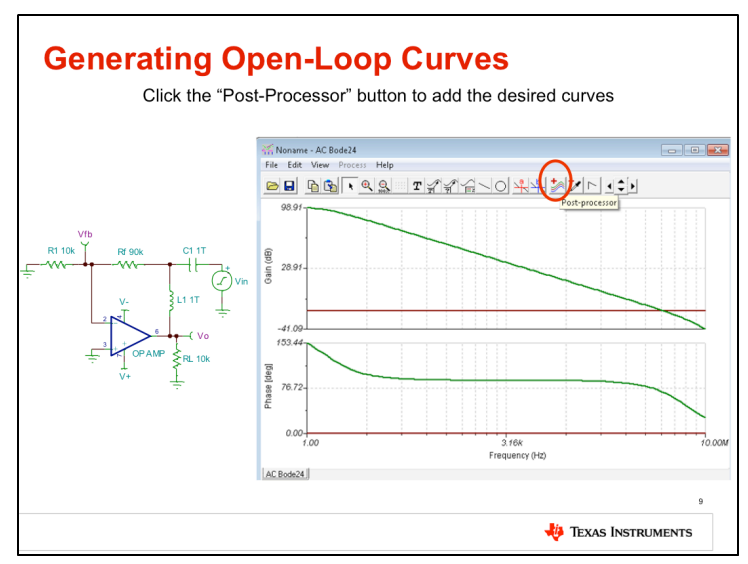
Although I learned on TI precision lab video 10.3 section, in simulation we should break the loop by using huge L and C in order to get loop-gain (as below), but  I have trouble on how to do this "break" on a howland circuit, because it is containing both negative and positvie feedback paths.

I searched on this forum and found this relaed original post(https://e2e.ti.com/support/amplifiers/f/14/t/678722) where  attached a 5047.OPA549 Howland Stability.pptxmay related to my question, but I did not understand the simulation configuration very well, hope some expert may help explain.

Any advice is welcome, thanks a lot !

  • Hi Yi,

    have you viewed the whole series of these TI's stability learning videos?

    Kai

  • Kai, I finished them except 10.7 lab. there is no infomation on howland circuits simulation, and that why I post quesitons here.

  • by the way, I also reviewed the fundamental knowledge of control system textbook, the key point is to convert the circuits into block diagram (or signal flow diagram), and dervie the transfer function of loop-gain, then use the bode plot of loop-gain to calculate phase margin. this is the basic and classic method for any stability problem.

    My question is on TINA simulation implemention, about how to use L and C in simulation to properly "break" the closed-loop of howland current soucre circuit. 

    Thanks.

  • indeed we could use in-direct way (as Video 10.4 teaches)  that using overshoot or gain peak to get Phase margin, but we prefer the classic bode plot method.

  • Hello Yi,

    A stability analysis of the Improved Howland Current Pump is highly involved and much more difficult than that for a simple voltage amplifier stage. That is because the pump relies on two feedback paths; one involving negative feedback, and the other positive feedback. Even with a purely resistive load a careful design is required to assure stability. The stabilization only becomes more questionable and usually more difficult when a complex load (R+/-jX) as being driven by the current pump.

    One of our former Precision Amplifiers team members worked to understand and provide a method for doing the stability analysis of the Improved Howland Current Pump circuit. The example power op amp circuit is driving a complex impedance load which is similar to what you want to do. I have attached slides from his TI Training presentation that he put together several years ago. The process he used for analyzing the stability is provided in the slides. I do not have any information beyond what is in the slides as they were presented live. Hopefully, there is enough detail to help you complete the analysis.

    Regards, Thomas

    Precision Amplifiers Applications Engineering

    Improved Howland Current Pump Stability_01.pdf

  • Hi Yi,

    can you show a schematic of your circuit? Or do you already have a TINA-TI simulation file?

    Kai

  • Something I found helpful when designing my own Modified Howland Current Source (before I even knew what it was called) was 1) by performing a sweep back into the output to see what the impedance was to the outside circuit, and 2) driving a transient voltage into the output to see the response.  Instabilities would show up there.

    Be sure to be careful about tolerance buildup depending on the values you use.  It's too easy to turn the (net) negative feedback amplifier into a positive feedback amp.  Improving resistor precision can help as well as adding some headroom to back down from ideal infinite output impedance back to a nominal design value.

  • Hi Yi,

    only an example:

    yi_opa548.TSC

    And here the phase margin:

    yi_opa548_1.TSC

    Kai

  • Hi Kai, thanks for showing me an example.

    I did some simulation on your TINA file, got good phase margin but bad transient response (square wave), then my working computer crashed down :( 

    So I will repaire my PC and post my TINA file and bode plots tomorrow. My SCH is the same structure with yours except for the RC values and power voltage, the numbers I used are below, for your reference.

    (1) U1 I use OPA564, and +/-Vs = +/- 10V

    (2) VG1 (input sine wave on R7 left pin) = 1.25V*sin(2*π*f*t) , f_max=500HZ

    (3) R2=R7=100k, R3=R1=3.3K, C1=4.7nF, R9=0, R6=0.15ohm,

    (4) I checked again with motor coil spec : L1 = 4.1mH and R8=8.5ohm (Sorry for the inaccurate value), and coil current should be <0.5A, and voltage across two terminals of coil should be <4.5V. which means I will need to measure Voltage on two pins of R6 and current in R8.  And I did not use C2 in simulation.

    All of your plots are  all quite good, may I ask how do you calculate / tune the C1 and R9 ? TI app notes (http://www.ti.com/lit/an/snoa474a/snoa474a.pdf) seems do not use R9 at all .And how did you choose  C2 ? Thanks.

    I would also build a bench test soon, too.

    Thanks a lot!

  • Hi Kai, here is my update. Attached TR and AC sim TINA files.  and motor coil spec.

    xy-TR.TSC

    xy-AC.TSC

    1. From AC analysis we can see the phase margin is good enough

    2. Transient response of 500Hz sine wave is good too, but the Vpp voltage on coil (Vout-load node in the SCH) is about 10Vpp, However , the bench test real waveform is about 18Vpp, this is confusing. This is far exceed the motor spec, I worried it would damage the coil

    The current Ipp is almost the same for simulation and bench test.

    3. Transient response for Square wave is really bad in simulation, compare with your plot.

    By the way, two OPA564 became very hot, and after I attached heatsink on the top pad, the temperature of the heatsink is around 50°C

    I would like to hear you comments, thanks again.

  • Hi Yi,

    will have a look at it tomorrow :-)

    Kai

  • OK, The output sine wave seems stable for now based on measured waveform,so I can wait, no hurry.

    I also notcied you replied on another post of mine related to THS4032, thank you again for helping.  

  • Hi Yi,

    have you thought about using a special stepper motor driver?

    Kai

  • Hi Kai,

    We use this motor drive circuits in 4D ultrasound probe drive system.

    Yes we indeed considered and compared PWM driver like DRV88xx series of TI with the linear drive solution in the early stage of our project, but we worried that PWM solution may generate more EMC interference whichi could jeopardize the 4D ultrasound image, so we use linear drive for first prototype and it works wells.

    The next step is optimize this howland current source circuits, such as system (power amp) stability analysis, thermal management and cost down for next HW version. This is where I come across the issue of amplifier stability quesitons and came to this forum to ask for help.

    How do you think my last post inluding the simulation and test waveform?

    Thanks !

  • Hi Yi,

    if I had to use the OPA564, I would take this as a starting point:

    yi_opa564.TSC

    yi_opa564_1.TSC

    Kai