This thread has been locked.

If you have a related question, please click the "Ask a related question" button in the top right corner. The newly created question will be automatically linked to this question.

INA122: INA122

Part Number: INA122

When measuring the resistance  from LoadCell_In- and LoadCell_In+ to ground the values are 75 ohm functioning board. On a failed board the values are 58 ohm. Also on a functioning board with zero volts on the LoadCell_In there is Zero volts on P04. On a failed board the value is 2.3 volts. What failure mode in the chip could cause these results?

  • Hi David,

    Please use the red circled icon to upload your image. 

    Best,

    Raymond

  • Hi David,

    I have received the your schematic file for INA122. I need more information from you about the failure. 

    Question:

    When measuring the resistance  from LoadCell_In- and LoadCell_In+ to ground the values are 75 ohm functioning board. On a failed board the values are 58 ohm. Also on a functioning board with zero volts on the LoadCell_In there is Zero volts on P04. On a failed board the value is 2.3 volts. What failure mode in the chip could cause these results?


    Summary about your schematic and issues:

    1. Single 5V rail with Vref=2.5V

    2. Gain = 5 + 200k/1.5k = 138.33

    3. When board is functioning, TP04 is measured 0V. Vout=0V at pin 6 means that LoadCell_In+ = LoadCell_In-. 

    4. In failed board (assume INA122 failed?), Vout = 2.3V. With Vout=2.3V,  LoadCell_In+  -  LoadCell_In- = Vout/Gain = 2.3V/138.33 = 16.6mV

    Please verify my understanding about the circuit. I need more information from you. 

    a. What is DC bias or input Common-Mode voltage at LoadCell_In+ and LoadCell_In-.

    b. I would assume that  scenario in 4 above is working, 3 may be not? Please confirm. 

    c. Is your LoadCell functioning? What type of load cells is this? You stated that from LoadCell_In- and LoadCell_In+ to ground the values are 75 ohm functioning board. Where is 75 Ohm from? 

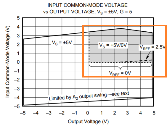
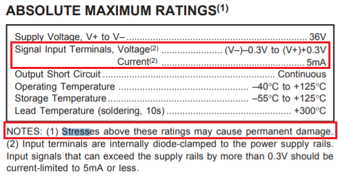
    Per the datasheet, the LoadCell_In+ and LoadCell_In- 's input common mode voltage has to meet the following requirements (gray area) in orange. 

    Please provide us with additional setup information. 

    BTW, please use the clip icon inside of Green circle when you want to load a file. To load image (png, jpeg etc.) is using the icon in red.  

    Best,

    Raymond

  • Hello Raymond,


    Please see my responses below. Some background information. We receive a failed circuit board from the customer and they ask us to determine the route cause of the failure. We do not have a test fixture to determine the functionality of the board. What we can do is measure the resistance on the external connections to the ground connections and apply power to the board. The resistance measurements on the LoadCell_in- and LoadCell_in+ connections to the ground connection are different on “new” boards and “failed” boards. All other resistance values are the same for “new” and “failed” boards . The loadCell_in- and LoadCell_in+ values on “new” boards are 75K ohm. The values on failed boards are 58K ohm.  We also apply power (24VDC) to the boards. A new board measures zero volts at TP04 and a failed board measures 2.3VDC.  These are the only tests we can conduct.  I know it is crude but it is all we can do. I hope you can help me understand what could possibly be the cause.  Thank you.


    Regards,

    Dave


    a. What is DC bias or input Common-Mode voltage at LoadCell_In+ and LoadCell_In-. During the test the LoadCell inputs were open. They were not connected to anything

    b. I would assume that  scenario in 4 above is working, 3 may be not? Please confirm. During the test the LoadCell inputs were open. They were not connected to anything

    c. Is your LoadCell functioning? The load cell was not connected. What type of load cells is this? There is no load cell You stated that from LoadCell_In- and LoadCell_In+ to ground the values are 75 ohm functioning board. Where is 75 Ohm from? The 75K ohm is on the PCB between the input pins and the IC.

    NCR56822 Analysis IMAGE and test setup.docx

  • Hi Dave,

    INA122 does not use input pin resistance measurement to characterize the part in its functionality. Since you are looking for root causes, one of the following method can provide evidences what is wrong with the board. Once damaged part is confirmed, we can investigate the possible causes.  

    1. If you are able to replace U06 or INA122 IC with a new part, you will confirm if INA122 is damaged.  

    2. Do you have datasheet for EZAE62A50A TVS? I am unable to get the specification online. Can you remove both V57 and V58 TVS from the inputs of INA122? I was wondering if one or both of them are damaged. The input impedance of INA122 is very high. Since  you measured 58kOhm vs. 75kOhm, I was wondering if TVS is damage somehow. INA122's input are protected with internal diodes connected to the power rails. Anyway, it is a possibility that TVS got damaged also.

    Remove V57 and V58 TVS,  if both input resistance are still measured at 58kOhm, it is likely that TVs are gone bad (not likely generally). 

    In addition, can you tell us more about the input voltage of the sensors, and its application environment. What types of transient conditions are present at the input of INA122? 

    Best,

    Raymond

  • I do not have a specification sheet for this device. I can not easily remove V57 and V58 from the PCM. They are surface mounted devices. I measure them both in the circuit using a multi meter. I measure resistance with proper (common lead on the ground terminal) and reverse (positive lead on the ground terminal) polarity. I did the same for the multimeter Diode mode. The measurement results are:

    Resistance proper polarity 56K ohm

    Diode mode proper polarity 0.96 volts

    Resistance reverse polarity 49K ohm

    Diode mode reverse polarity 0.857 volts

    Doe this tell you any thing? Do I need to remove the devices?

    The in put voltage is 2 - 7 millivolts

    Regards,

    Dave

  • Hi Dave,

    Since TVS is connected in parallel with 75kOhm resistor, it is difficult to use resistance value to diagnose the issues. Please ask your technician to perform the following test sequences. 

    1. Remove INA122, then clean the IC pads. 

    2. Measure Resistance again  from LoadCell_In- and LoadCell_In+ to ground.  Record both R values. 

    3. Replace INA122 with a new part, and check the board performance. 

    I need to confirm which parts are damaged before I am able to make suggestion and/or recommendation. Also, please feed me as much information you have about the input voltage of the sensors, and its application environment. What types of transient conditions are present at the input of INA122

    Best,

    Raymond


  • Hello Raymond,

    Unfortunately we can not replace the INA122. Do you still want me to remove the INA122? I am working in an office cube and have limited access to tools?

    Regards,

    Dave

  • Hi Dave,

    You may have to go to production area, and find a technician to assist the rework. This may be the quickest way to find out if INA122 is damaged from in circuit testing, since you do not have sensor's input and transient information and behaviors. 

    By the way, how many units do you have with similar issues as in this INA122 board?

    Best,

    Raymond

  • Hi David,

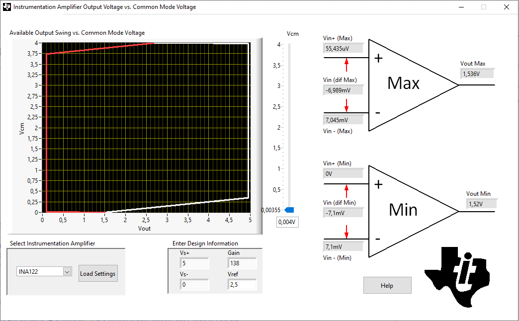
    the INA122 will not properly work with its input pins being unconnected because the input voltage (0V) is outside the common mode input voltage range:

    Because of this your measurements aren't very helpful, unfortunately.

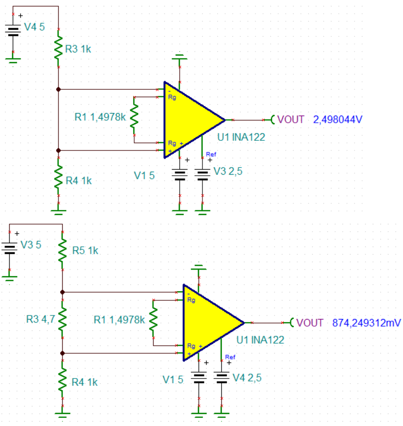
    I would recommend a measurement which provides a common mode voltage of 2.5V to both inputs:

    Can you connect some resistors to the inputs of circuit as shown below and measure the output voltage of INA122?

    david_ina122.TSC

    Kai

  • Hi Dave,

    We haven't heard from you in a while. We hope the issue was resolved. Closing this thread now. Reply to re-open if you have any additional questions.

  • Hello Tamara,

    Thank you for the email. I returned the PCB to the manufacture and had the chip U06 (INA122) removed. I measured the input circuit resistance. It measured 75 K ohms the same value as a properly functioning circuit.. When the chip was installed the input resistance measured 58 K ohms. Please help me understand what could have failed in the chip.

    Regards,

    Dave

  • Hi Dave,

    have carried out the measurements I have recommended in this post?

    Kai

  • Hi David,

    Please follow the Kai's measurement suggestions in U6 of INA122. 

    Question:

    I returned the PCB to the manufacture and had the chip U06 (INA122) removed. I measured the input circuit resistance. It measured 75 K ohms the same value as a properly functioning circuit.. When the chip was installed the input resistance measured 58 K ohms. Please help me understand what could have failed in the chip.

    Based on the your test, it is likely that U06 IC in INA122 has been damaged. This is not surprising, since you had suspected that was the case. It was not conclusive from your early resistance and short circuit measurement. If you follow Kai's suggestion, you will confirm that the INA122 has gone bad. 

    INA122 has very high input impedance. Although we do not use input DC measurement to determine the functionality of INA122, the DC resistance in your good INA122 board should be measurement approx. 75kOhm in your circuit. With DC resistance measured at 58kOhm, there is another resistive path to ground at INA122's input. Based on the calculation, a resistive path with  approx. 255.8 kohm is somehow in parallel with 75 kOhmm resistor at the input of INA122. 

    If you are able to replace INA122 IC at U06 in the damaged board, the board should work again. 

    In order to find the root causes, we need to know the detailed information about the differential inputs of INA122 from your customer. Such sensor configuration and its operating conditions are: 

    1. What is INA122's in use application?

    2. What is the input DC biased voltage? What types of input sensors are these?

    3. What types of transient conditions are presented at the INA122's front end.

    4. Do you have sensor's schematic?

    5. How many damaged INA122 boards do you have? Is this frequent occurrence? 

    6. What is the operating temperature environment? 

    7. Under what operating conditions in which the board is damaged etc.

    If you are able to provide these details, we may be able to find the root causes. 

    Best,

    Raymond


    • Please read the responses below. I wished I could supply more details but our customer will not provide the operating condition that resulted in the failure (they may not have that information). Please look at the internal design of the chip and see if you can determine what would result in a 255.8 Kohm resistance to ground that you have calculated. Thank you

      In order to find the root causes, we need to know the detailed information about the differential inputs of INA122 from your customer. Such sensor configuration and its operating conditions are: 

    1. What is INA122's in use application? The INA122 is used to amplify an input signal in the range of 2-7mV

    2. What is the input DC biased voltage? The supply voltage is 10VDC. What types of input sensors are these? Please see this information below

    TRANSDUCER TECHNIQUES MODEL: SB0-3K

    LOAD CELL, PRECISION, TENSION CALIBRATED 3,000 LB CAPACITY, 1/2-20 UNF THREADS

    3. What types of transient conditions are presented at the INA122's front end. Unknown

    4. Do you have sensor's schematic? No, please check the suppliers web site. See answer 2.

    5. How many damaged INA122 boards do you have? We have 7. Is this frequent occurrence? Yes 7 have failed in 6 months.

    6. What is the operating temperature environment? This is a rail road application. The specification are -40F to 100F

    7. Under what operating conditions in which the board is damaged etc. Unknown, the customer will not supply that information.

    If you are able to provide these details, we may be able to find the root causes. 

    Regards,

    Dave

  • Hi Dave,

    Thanks for the more information. Now we have some information to go on. 

    Were the input resistances on both input pins of INA122 measured at 58kOhm? Please confirm this.

    Have you verified that the measurement technique described by Kai in the previous reply. I would like to know, what will be the output, if the DC bias voltage was placed at its input. I want to know how badly INA122 is damaged. 

    This is a locomotive application. The excitation voltage to the transducer is 10Vdc. The load cell is SOB-3K-C type (Compression), and some cell specification can be found in the following site. 

    https://www.thomasnet.com/catalogs/item/354471-8357-1019-1297/transducer-techniques-llc/sbo-series-3000-pound-lb-capacity-universal_tension_compression-precision-beam-load-cell/

    The nominal transducer's resistance is 350 Ohm. Let us assume that this is wheatstone bridge sensor configuration, the maximum input current through the bridge is 14.29mA.  And the input DC bias or Vcm at INA122's input is 5*75k/(75k+348)=4.977V.

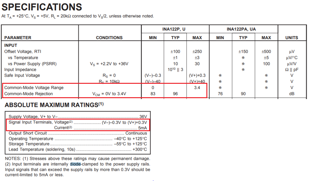
    From the datasheet, the max. Vcm for INA122 should be configured below 3.4V. Since the application is configured at 4.977V, this may be a reason that the part is damaged prematurely due to EOS. In addition, the max. input current in INA122 should be limited to 5mA. The schematic is shown that the input current may go up to 14mA or so. 

    I think that we may be able to change some resistor values and fix the issues. Please let us know how you'd like to proceed. 

    By the way, all the damaged components are repairable. If this is indeed due to EOS, it can be fixed readily. 

    Best,

    Raymond

  • Hello Raymond,

    Thank you for the information. Yes both input pins measures 58KOhm. I had the board manufacture remove the INA122 chip and both inputs measured 75KOhm. Is this the measurement Kai requested? Please let me know.

    If you can make some suggestions on how the circuit can be modified please do.

    Regards,

    Dave

  • Hi Dave,

    The following tests are what Kai recommended to verify the INA1222 is damaged. 

    Let me get back to you the remedy on monday. Your issues can be resolved by changing the resistor values, but I'd like to do the minimum changes to fix the issues. Meanwhile, can you verify of my speculation is correct and the "damage" of INA122 is likely due to EOS?

    Best,

    Raymond

  • Hello Raymond,

    I do not have the equipment to conduct these tests. The chip has been removed from the board. I have the chip. I can ship it to you if you would like to conduct the tests. Please let me know.

    Regards,

    Dave

  • Hi Dave,

    I contacted the transducer's manufacture (Transducer Techniques, LLC), and It is likely that the "damaged INA122" is a case of Electrical Over Stress at input based on the information that you are given, and manufacture's datasheet + support. 

    /cfs-file/__key/communityserver-discussions-components-files/14/INA122-SOB_2D00_3K_2D00_C-07272020.TSC

    Here are two modification options, I'd like you to make a decision.

    1. If SB0-3K transducer's excitation voltage is reduced from 10.0V to 5.0V, then no circuit modification is required. 

    2. If you want to leave the transducer's excitation voltage unchanged, we have to change the resistor values at INA122's input. 

    Here is the justification from case #1.

    The SB0-3K transducer is rated from 0-3000 lb of compression forc, and it has nominal rated output at 3mV/V. In addition, the sensor's excitation voltage can be selected from 1-12V based from the manufacturer's support. 

    At Vexcitation = 10V, the maximum differential sensor's output is 3mV/V*10V=30mV, At the differential 30mV, the compression force is proportional to 3000 lb. 

    With application input range of 2-7mV, the application is measuring the compression force range form 200 lb to 700 lb per the application. 

    If you are using Vexcitation = 5V, the maximum differential sensor's output is 3mV/V*5V=15mV, where 15mV represents 3000lb of compression force. 

    Therefore, if the Vexcitation=5V is used, the transducer's differential output will be from 1mV to 3.5mV. 

    With Gain=138.33 V/V, For 1mV input, Vout = 2.5 + 138.33V/V*1mV= 2.638V. For 3.5mV, Vout = 2.5V + 138.33V/V*3.5mV = 2.98416V. 

    The software or display may have to be modified.

    In the case #2 above, with resistor value changes at input, the INA122's output voltage will be different from before, and you still have to change the software or display that reports the compression values as well, also, you will require to do modification on very boards in the field. 

    Best,

    Raymond

  • Thank you for the information. Please let me know what components inside the chip could be responsible for the 58K Ohm parallel resistance to ground. Thank you.

  • Hi David,

    The INA122 is operated at 5Vdc and Ground. The load cell's excitation voltage is operated at 10Vdc and Ground. Two electrically overstressed conditions happened in the design application.  

    1. Load cell's Input voltages at Vin+ and Vin- exceed the maximum allowed input Common-mode Voltage of 3.4Vdc. 

    2.  The input current at Vin+ and Vin- may be as high as 7.2mA, if input terminal voltage is greater than (V+)+0.3V during power up, power down or transient power interrupt events. The current in the clamping diodes should be less than 5 mA under these events.  

    Without X-ray image analysis, it is hard to say which one is damaged first. The over voltage stress over input pins in scenario #1 are occurring constantly. Hence, I will speculate that the input impedance at Vin+ and Vin- are damaged due to the EOS. The nominal input impedance of Vin+ and Vin- are rated 10^10 Ohm. The EOS may create some kind of short at its input, and create parallel resistive path to ground in an order of 255 kOhm.

    Best,

    Raymond

  • Hello Raymond,

    There was a suggested solution to change the resistance on the input to the chip. Please let us know the value of the resistors we should use.

    Regards,

    Dave

  • Hi Dave,

    Yes, If your customer wants to leave 10.00V excitation voltage alone, then one of the option is to change two resistor values. I am talking about the minimum modification at this point. 

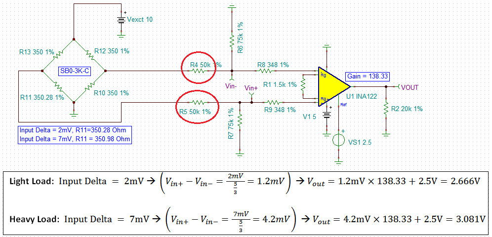
    The INA122's input Vcm voltage is changed from 4.97Vdc to 3.00Vdc., which is within the required 0 < Input_Vcm < 3.4Vdc range. 

    With the change, you still have to change the equation in the software to reflect the load conditions at the sensor. 

    The SB0-3K transducer is rated from 0-3000 lb of compression force, and it has nominal rated output at 3mV/V. With excitation voltage = 10.0V, 30mV represents 3000 lb in full load scale. With 2mV delta change at the transducer, it is equivalent to 2mV/30mV*3000 lb = 200 lb or Vout = 2.666V. with 7mV delta change at the transducer, it is equivalent to 7mV/30mV*3000 lb = 700 lb or Vout = 3.081V.  Without the load or 0 lb, Vout = 2.50V. 

    /cfs-file/__key/communityserver-discussions-components-files/14/INA122-SOB_2D00_3K_2D00_C-08192020.TSC

    If you have other questions, please let me know.

    Best,

    Raymond