This thread has been locked.
If you have a related question, please click the "Ask a related question" button in the top right corner. The newly created question will be automatically linked to this question.
Hello,
I am trying to use the charge amplification circuit from TI (link:- https://www.ti.com/lit/an/sloa033a/sloa033a.pdf page-4 ) for my sensor (https://www.mouser.com/ProductDetail/824-1-1000288-0 ). The problem is sometimes the circuit works fine and gives an appropriate output based on my sensor signal and sometimes it is just giving me a 5V output irrespective of my sensor signal. My supply voltage is 5V to the opamp.
Can you please help in decoding the problem. Thank you.
Hi Parth,
Could you please provide a schematic? Also, would you mind providing information about your input signal, expected output signal, and any debug you may have tried so far? So, you have have the V- pin to GND and the V+ pin to 5V, correct?
Sounds like you're output is railing at times. Could be a number of things, such as an issue with violating the common-mode input voltage specification, too much gain, etc.
Regards,
Daniel Miller
Hi Daniel,
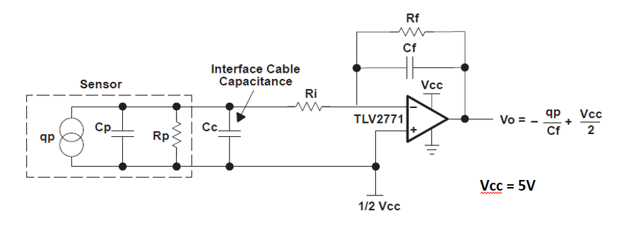
Please find the schematic below. I am using a piezoelectric sensor so it will give a voltage response based on the applied mechanical load. the voltages are in 10- 100 mV. yes the V+ is 5V and V - is ground. The positive of my sensor is connected to Vin- and negetive is connected to Vin+ along with 2.5V supply.
Can you explain what is meant by the output being railing at all times?
Hi Kai,
Please find the part values. I hope this is what you require.
Rf = 10 G Ohm
Cf = 1 nF
Ri = 0
Cp + Cc ~ 3 nF
Rp ~ 0
Hi Parth,
oops, Rf and Cf are creating a huge time constant of 10 seconds :-)
This can paralyze the OPAmp for many seconds.
Do you want to measure the sensor signal? Or do you only want to detect whether the signal is above a certain threshold?
Kai
Hello Parth,
By "railing" I mean that the op amp's output is stuck at the voltage level of one of the two supply rails, in this case the 5V Vcc rail.
In addition to answering Kai's question, could you let us know what your expected signal frequency will be or what range of signal frequencies will be used?
Regards,
Daniel
Kai I would like to measure the signal. I have been able to use the same configuration to measure it once but now in the same configuration I am not able to.
Daniel, I am using the sensor to measure forces while machining so I don't have a range of frequency which the signal would undergo. Does it mean that because of the input signal having a higher amplitude the op amp output is large and it gets cutoff at 5V?
Parth
Hi Parth,
Apologies for the delay in my reply. Thank you for your patience.
It can happen for a variety of reasons, for example if you have too much gain then the output will go all the way up to the rail and stop there.
I would take Kai's suggestion and start by reducing the resistance of the Rf component by a few orders of magnitude. Also consider that, with Rf being as large 10GOhms, it is really more like an open circuit than an actual resistive path.
Regards,
Daniel
Hi Daniel,
Thank you for your reply. It seems that there is some EM interference due to a machine nearby and that is why it is giving me the railing output. Do you have an idea as to how can I reduce it before giving the input to the opamp?
I understand that it is making an open circuit however for my application I require these values.
Thanks and regards,
Parth
Hi Parth,
I agree with Daniel. I also would decrease Rf. Why? 10GOhm and 1nF give a low pass filter with a corner frequency of 1 / 2 / pi / 10GOhm / 1nF = 0.016Hz. Is this really what you want?
You could use a much smaller Rf and increase the bandwidth by this. Additional gain can be provided by an additional gain stage.
Also, the datasheet of sensor seems to recommend voltage mode amplification, not charge mode.
Kai
Hi Parth,
In addition to Kai's comments, I would say that EMI can be filtered out but you'll need to have some idea of what is generating it or what frequency it is operating at. Do you have any information on how this issue is being created?
Regards,
Daniel
Hi Daniel,
Sorry for the late reply but I don't have an idea as to what frequencies are causing the problem. However currently I am able to get the results as I want and it seems to have solved the problem on its own.
Thank you so much for your help Daniel and Kai. Let me know if you have any other questions.
Thanks and regards
Parth
Hello Parth,
I am happy to hear that your issue seems to have been resolved. Feel free to post again if you need any more help.
Regards,
Daniel