Because of the Thanksgiving holiday in the U.S., TI E2E™ design support forum responses may be delayed from November 25 through December 2. Thank you for your patience.

This thread has been locked.

If you have a related question, please click the "Ask a related question" button in the top right corner. The newly created question will be automatically linked to this question.

Capacitance sensing architecture

Other Parts Discussed in Thread: FDC1004, OPA132, INA188, INA154

Hi,

    I need to sense precision capacitance change of a resonant sensor. The signal is having bandwidth greater than 25 KHz. Hence standard CDC cannot help. I am planning to realize the sense circuitry with an opamp. Please help with the following.

1) Which architecture is preferred viz Charge amplifier, TIA or Normal Buffer amplifier (Switched capacitor architecture is not selected)

2) Which parameter of the opamp is critical, the bias/offset current, voltage noise or current noise.

    Any application note to throw light on above queries.

   Thanks in advance

       Karthik R

  • Hi Karthik,

    can you share a datasheet of this sensor?

    Kai

  • Hi Kai,

     Thanks for the reply. It's not an off the shelf product but a MEMS capacitance sensor. I can share any particular parameter of the sensor if you need.

       Thanks

            Karthik R

  • Hi Karthik,

    yes, please :-)

    Kai

  • Hi Kai,

      Thanks for the reply. To start with, the base capacitance will be less than 25 pF range and maximum change in capacitance will be less than 10%. The rate of change of capacitance will be at 25 KHz as mentioned in the query. I need to digitze the capacitance change. Hope this will suffice now.

       Regards

         Karthik R

  • Hi Raymond,

      Thanks for the reply.

    Raymond Zhang1 said:
    There are so many capacitive touch sensing methods these days.

     Yes but most of these touch sensors have lesser bandwidth requirements I guess.

    [quote user="Raymond Zhang1"]www.ti.com/.../tidu736a.pdf

    It is based on FDC1004 which has output rates in few Hz whereas in our case, the change in capacitances will be in few KHz itself inaddition to higher carrier frequencies given for excitation.

    Regards

        Karthik R

  • Hi Karthik,

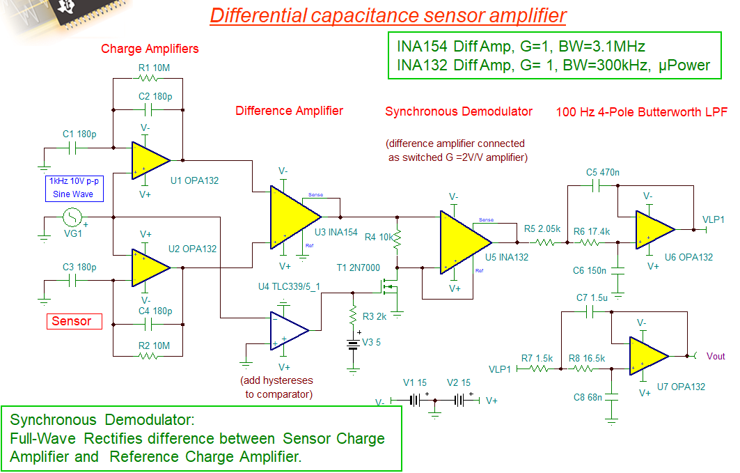
    What are the voltage rails like in your capacitive sensor application (dual or single rail)? I found the following slide, which it may help you to detect up to 2.5pF changes. Are you looking for passive sensing at the touch pad? 

    I am sure that there are other options. Please let me know what you think. 

    Best,

    Raymond

  • Hi Raymond,

       Thanks for the reply.

    Raymond Zhang1 said:
    What are the voltage rails like in your capacitive sensor application (dual or single rail)? I found the following slide, which it may help you to detect up to 2.5pF changes. Are you looking for passive sensing at the touch pad?

     Voltage rails we are planning is +/-5V. The application is not a touch pad sense but for a resonant sensor.

    Raymond Zhang1 said:
    I am sure that there are other options. Please let me know what you think. 

    Thanks for the circuit. In this, I need only the front end OPA132 circuits since rest I have planned in digital domain. This a charge amplifier implementation. Just want to know whether this circuit is the best option for low noise capacitance sensing since other circuits TIA, Buffer amplifiers are available. www.mmf.de/instrumentation.htm_section1.2

    Also for the front end opamp (in this case OPA132) whether the noise for bias current is more critical.

    Thanks and regards

       Karthik R

  • Hi Karthik,

    Do you have your resonant sensor with L&C parameters and equivalent PSpice model? Perhaps we can simulate potential circuits. Are you talking about inductive sensing rather than capacitive sensing? 

    FDC1004 may be a proximity or gesture sensor. I am not familiar in this particular part (different application group) The sensor's front end may be frequency based, and a digital counter is accumulating the counts from capacitive sensing and make 1 or 0 decision based on the counter's threshold. It can be very sensitive, but it can also be too sensitive (may cause false positive sensing, and require baseline calibration) due to changes in the environment, such as temperature change, air current flow, A/C, bugs etc..

    Max. 2.5pF delta out of 25pF total is fairly small change. That is why I think that differential sensing circuit may have better chance. TIA sensing as the front end may work as well, but we have to convert the resonant sensing into current. I am not sure about buffer amplifiers for this application. 

    From OPA132 datasheet, you can see the op amp requirements for the application. 

    1. ultra low Ib current and low offset voltage 

    2. low voltage and current noise

    3. low voltage offset drift over temperature

    4. High slew rate and high Open loop gain

    5. possibly 1/f noise per your sensing application. 

    Best,

    Raymond

  • Hi Raymond,


    Raymond Zhang1 said:
    Do you have your resonant sensor with L&C parameters and equivalent PSpice model? Perhaps we can simulate potential circuits. Are you talking about inductive sensing rather than capacitive sensing?

       I am referring to capacitance sensing only. I will generate the equivalent L & C.

    Raymond Zhang1 said:
    FDC1004 may be a proximity or gesture sensor. I am not familiar in this particular part (different application group) The sensor's front end may be frequency based, and a digital counter is accumulating the counts from capacitive sensing and make 1 or 0 decision based on the counter's threshold. It can be very sensitive, but it can also be too sensitive (may cause false positive sensing, and require baseline calibration) due to changes in the environment, such as temperature change, air current flow, A/C, bugs etc..

      I am not looking into this part since the bandwidth is very less for my application

    Raymond Zhang1 said:
    Max. 2.5pF delta out of 25pF total is fairly small change. That is why I think that differential sensing circuit may have better chance. TIA sensing as the front end may work as well, but we have to convert the resonant sensing into current.

    Yes but the capacitance is single ended and it cannot be made differential.

    Raymond Zhang1 said:
    I am not sure about buffer amplifiers for this application.

    It is similar to this.  https://www.mmf.de/instrumentation.htm section 1.2.

    Raymond Zhang1 said:
    From OPA132 datasheet, you can see the op amp requirements for the application. 

    Yes but some of these requirements are contradictory. Like lower bias current comes with higher noise and viceversa. So I wish to know which parameter should be given more importance.

    Regards

       Karthik R

  • Hi Karthik,

    shall the sensor oscillate at 25kHz during the measurement? If yes, how do you make it oscillate?

    Kai

  • Hi Karthik,

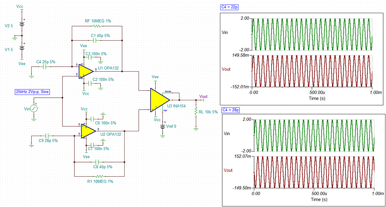
    Since the following circuit is charge amplifier, the current sensitivity is the most important. 

    I did a quick simulation, and it seems that it can detect a change of +/-3pF from the nominal of 25pf. The circuit may need some optimization, since I am unable to increase the gain by deceasing C1 and C8 capacitance in the circuit. 

    /cfs-file/__key/communityserver-discussions-components-files/14/OPA132-Cap-Sensor-07102020A.TSC

    Best,

    Raymond

  • Hi Raymond,

       Thanks a lot for performing the simulation. One doubt, if C4=28pf=C9, the U1 and U2 output should be same ryt. Then U3 output should be zero. Please correct if wrong.

    My concern is that if the amplifier is having higher bias currents, it will result only as a low frequency offset which can be compensated or low pass filtered, right ?. However the noise we cannot filter as such. So whether noise or bias/offset current is a bigger concern here,

       Regards

         Karthik R

  • Hi Karthik,

    again: Shall the sensor oscillate at 25kHz during the measurement? If yes, how do you make it oscillate? Or is it oscillating by itself?

    Kai

  • Hi Kai,

      Extremely sorry. I missed the question earlier. The sensor will oscillate at its resonance frequency typically 10 KHz based on the actuation signal. However to enhance the capacitance sensing, its better to modulate the vibrating signal with a carrier frequency (typicaly 100s of KHz). The sensor wont oscillate at this higher frequency however the current signals from the sense capacitance will have the capacitance change (due to 10 KHz resonance frequency) modulated onto the carrier frequencies (100s of KHz). Hope its clear now.

       Thanks and Regards

            Karthik R

  • Hi Karthik,

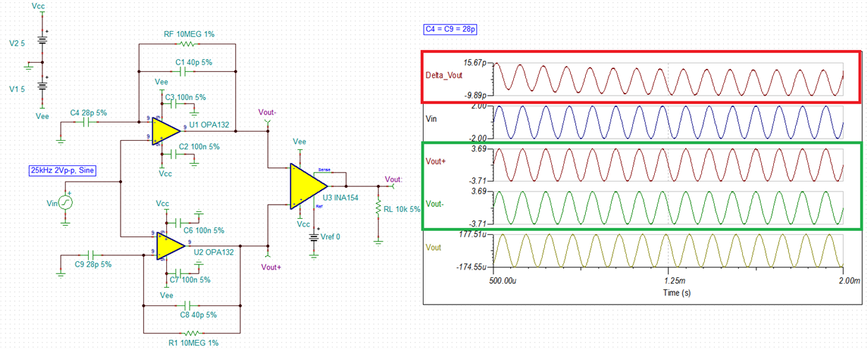
    One doubt, if C4=28pf=C9, the U1 and U2 output should be same ryt. Then U3 output should be zero. Please correct if wrong.

    My concern is that if the amplifier is having higher bias currents, it will result only as a low frequency offset which can be compensated or low pass filtered, right ?. However the noise we cannot filter as such. So whether noise or bias/offset current is a bigger concern here,


    I replaced Cr=C9=28pF as you requested, run a simulation with difference of Vout+ - Vout-, the differences are small, which means we may be able to improve INA154 with lower Vos difference amplifier, which likely will have better performance. For instance, if we replace INA154 with INA188 instrumentation amplifier, then it will resolve much of your concerns. 

    However, this is capacitive sensor, which is going to be very sensitive to environmental changes. You have to build in some sorts of calibration circuit (zero-out the differences) and time based auto sensing calibration to minimize the dVos/dt drift over time. Since you mentioned that you are going to digitize the signals, such changes in environmental conditions can be readily nulled out to improve the sensor's reliability and sensing accuracy. 

     Initially, the following circuit was a recommendation. If this differential capacitive sensing will work for you, we can make some improvement. 

    Best,

    Raymond

  • Hi Karthik,

    how do you make the sensor oscillate at hundreds of kHz? Do you need an electronic oscillator for this or is done by mechanical stimulation?

    Kai

  • Hi Karthik,

    We haven't heard from you in a while. We hope the issue was resolved. I am going to close this thread. Please reply to reopen if you have any additional questions / information.

  • Hi Tamara,

       I am not getting much inputs from the thread. So you may please close the thread

         Regards

           Karthik R

  • Hi Karthik,

    Is there anything else we are able to help in your design input?

    Previously, Kai asked the following questions: 

    how do you make the sensor oscillate at hundreds of kHz? Do you need an electronic oscillator for this or is done by mechanical stimulation?

    I demonstrated a design concept in simulation that you are able to sense 2-3pF capacitive changes at 25kHz in a differential sensing circuit.

    If you are able to provide us with more information about your design input,  perhaps we can help you further. 

    I am going to close this inquiry. Please reply to reopen if you have any additional questions / information.

    Best,

    Raymond


  • Hi Raymond,

      Thanks for the reply.

    Raymond Zhang1 said:
    how do you make the sensor oscillate at hundreds of kHz? Do you need an electronic oscillator for this or is done by mechanical stimulation?

    I had mentioned this in the previous reply as 

    Karthik Raveendranath said:
    However to enhance the capacitance sensing, its better to modulate the vibrating signal with a carrier frequency (typicaly 100s of KHz). The sensor wont oscillate at this higher frequency however the current signals from the sense capacitance will have the capacitance change (due to 10 KHz resonance frequency) modulated onto the carrier frequencies (100s of KHz). Hope its clear now.

    Also my actual queries were

    Karthik Raveendranath said:

    1) Which architecture is preferred viz Charge amplifier, TIA or Normal Buffer amplifier (Switched capacitor architecture is not selected)

    2) Which parameter of the opamp is critical, the bias/offset current, voltage noise or current noise.

    Any application note to throw light on above queries.

    since I didnt get any specific input to these queries. I thought I will study these circuits in detail and come back.

       Regards

         Karthik R

  • Hi Karthik,

    you wrote:

    The sensor will oscillate at its resonance frequency typically 10 KHz based on the actuation signal. However to enhance the capacitance sensing, its better to modulate the vibrating signal with a carrier frequency (typicaly 100s of KHz). The sensor wont oscillate at this higher frequency however the current signals from the sense capacitance will have the capacitance change (due to 10 KHz resonance frequency) modulated onto the carrier frequencies (100s of KHz). Hope its clear now.

    I'm sorry but nothing is clear to me. Because of this I asked these questions:

    How do you make the sensor oscillate at hundreds of kHz? Do you need an electronic oscillator for this or is done by mechanical stimulation?

    I still don't know what your "actuation signal" is. To be honest, I have absolutely no idea what you are doing and what support you are asking for :-)

    Kai