Other Parts Discussed in Thread: OPA388
Hello,
The part OPA388IDBVR.We test the part failed.Can you help us check with it?
Thank you.OPA388IDBVT report.docx
This thread has been locked.
If you have a related question, please click the "Ask a related question" button in the top right corner. The newly created question will be automatically linked to this question.
Other Parts Discussed in Thread: OPA388
Hello,
The part OPA388IDBVR.We test the part failed.Can you help us check with it?
Thank you.OPA388IDBVT report.docx
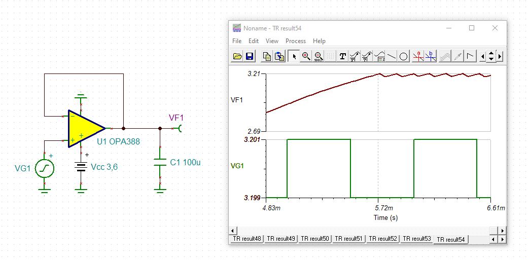
Hi Liuyamei,
As Kai pointed out, the circuit is unstable because it is attempting to drive a large capacitive load (~100uF). For this circuit to drive a sine wave you will need to greatly reduce the capacitance at the output. Your layout also includes a 0 ohm resistor (R5) that can be replaced with an isolation resistor for greater stability.
Zach Olson
Hi May,
Op Amps have issues when driving capacitive loads. It introduced another poles within the feedback loop. Generally, op amp will have a single pole roll off at -20dB/decade. If a second pole is generated within the feedback loop, it rolls off at -40dB/decade, which it will create instability --> your output will start to oscillate if small or large changes are occurred or triggered at input.
It looks like that you are using OPA388 as precision regulator. If you want to drive such large capacitive load, the OPA388 has to be well compensated. What are the load impedance at the output? What are the sourcing current?
3.2V and 3.3V are not off by much. It looks like that this is image sensor application. Are you trying to use OPA388 to limit the sourcing current at various pins of the CMOS/CCD sensor?
Best,
Raymond