This thread has been locked.

If you have a related question, please click the "Ask a related question" button in the top right corner. The newly created question will be automatically linked to this question.

Op Amps: Bandwidth

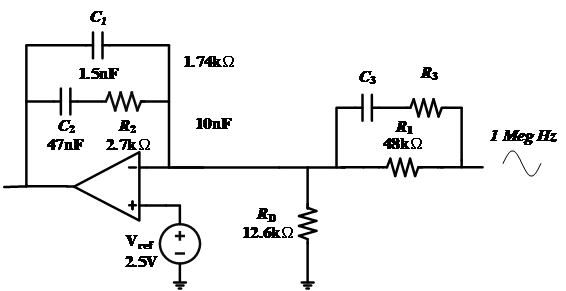
The Op Amps Bandwidth will affect by resister(Rf) and capacitor(C1), and I can know the cut off frequency is 1/(2*pi*Rf*C1),If I use typeIII the bandwidth will change if can change how do I calculate the cut off frequency

  • What is "typeIII"?

    Can you give us a schematic?

    Kai

  • Former Member
    0 Former Member in reply to user6349971

    Hello,

    Could you please show us where you found this circuit?

    Also, is "Vo" the input signal?  I think this circuit will have biasing issues because Vref will be setting the voltage at IN+ while Vo will be setting the voltage at In- through R1 and R4.  Assuming these voltages are different, which I think is a safe assumption, then the inputs of the amplifier will be pulled apart and the output will go to one of the output rails.

    It would be nice to see the original document in case there is something I have not considered.

    Regards,

    Daniel

  • This is circuit is TI document about compensator and My question is I need a high bandwidth op Amp, I watch the Ti training 

     TI Precision Labs - Op Amps: Bandwidth
     In the Video the bandwidth is limited by CF and RF 
     When I use the Type III compensator the bandwidth is limited by which component ? 


  • Former Member
    0 Former Member in reply to user6349971

    Hi,

    Have you taken a look at pages 8 to 10 of this app note?  It should cover all your questions regarding the locations of the poles and zeroes.  As for my previous comment about the voltage at the inputs to the amplifier, I think the answers to that question are on page 2.

    Regards,

    Daniel

  • I think you misunderstanding my means 
    my means is how do I decide the op amp bandwidth I watch the video about op amp bandwidth  like this 
    in the video the Bandwidth limiting is related to Cf and RF 
    IF my circuit is TYPE III the Bandwidth is who 
    and if I want to my bandwidth up to 1M how do I chose

  • Former Member
    0 Former Member in reply to user6349971

    Ok.  I think I understand now.

    To select a part with the right bandwidth, you have to take the bandwidth you want and multiply it by the gain you want.  This will give you a gain bandwidth product, "GBW".  Then, you need to search for an op amp that has at least that much GBW.

    It is a good idea to have some margin some margin, because the data sheet GBW is only a typical specification.  The real world value is different for each unit.  Some people recommend you multiply by 10x.  For example, bandwidth = 10kHz, Gain = 10V/V => 10kHz x 10V/V x 10 = GBW of 1MHz.

    To learn more, you might want to watch this video.

    Regards,

    Daniel Miller

  • Thanks I have watched the video 
    and I have some questions

    Gain = 10V/V is the non-inverting Gain right? 1+Rf/R1  the Gain can easily be calculated is using non-inverting

    but if my circuit is like type III there is no dc gain in this situation how do I calculate the bandwidth 

  • Former Member
    0 Former Member in reply to user6349971

    Hi,

    What I would in this case is use fp2 (see one of my previous posts) as the point of interest.

    Regards,

    Daniel

  • you mean the cut off frequency is determined by fp2?

    the op amp bandwidth is determined by non-inverting gain    if non-inverting gain =20 GBW=20Meg so the bandwidth is 20Meg/20=1M

    but when I use typeIII how do I know where is my non-inverting gain? If I don't know the non-inverting gain how do I know the bandwidth ?

    sorry this question is confused to me for a long time

  • The app note addresses to experts, but not to newbies.

    As the frequency response of type III compensator is highly wavy and not constant at all, please first define what you mean by "inverting gain" and "bandwidth".

    Kai

  • Yes  the Type III compensator  is not constant at all , so 
    1) In the Ti op amp datasheet the bandwidth is determined by non-inverting gain times bandwidth = GBW ?
    2) if the GBW is based on the  non-inverting gain times bandwidth = GBW   when I use type III compensator how do I calculated GBW

    3) If I  a signal which frequency is 1MegHz how do I choose my OPA and I  want the signal  can pass the opa 

  • Former Member
    0 Former Member in reply to user6349971

    Hi,

    The GBW of an op amp is intrinsic to the op amp. It does not depend on the circuit. The circuit will determine the gain and the frequency at which the gain is achieved. You then want to make sure your op amp has enough GBW to cover this gain and bandwidth. To verify this, multiply the gain that you want in V/V by the frequency at which you want this gain in Hz. Whatever this number comes out to be, you need a part with a GBW that is higher.

    For the type III compensator, I would take the frequency of fp2 and the gain of fp2 and multiply these values together. Then, pick an amplifier that has a GBW that is greater than this number. The location of fp2 is picked by design.

    If your signal of interest is 1MHz, then you need to figure out how much gain you want at that frequency. For example, if you want a gain of 5V/V for a 1MHz signal, then the op amp you pick needs a GBW > 5MHz.

    Regards,
    Daniel

  • Hi,

    first, I would calculate the noise gain of the type III compensator:

    type3compensator.TSC

    Then, I would search for the maxima and add 20dB of linearizing gain reserve.

    8dB + 20dB at 20kHz translates to a minimum unity gain bandwidth of OPAmp of about 500kHz.

    0dB + 20dB at 1MHz translates to a minimum unity gain bandwidth of OPAmp of 10MHz.

    So if your input signal bandwidth is 1MHz, I would choose a 10MHz OPAmp.

    What is your input signal bandwidth?

    Kai

  • Sorry, I can't understand why need ti add 20dB

  • Former Member
    0 Former Member in reply to user6349971

    Hello,

    The recommendation of +20dB is made to give you design margin.  This is done because not all amplifiers have exactly the GBW given in the data sheet.  There is some variation from unit to unit.  Variation can also occur with temperature.  So the data sheet value is a typical value.

    It is a good idea to leave room margin in the design and +20dB.

    Kai, please correct me it I have misunderstood your intentions.

    Regards,

    Daniel

  • Your mean is if I need the gain 20dB and the badwidth 500kHz so I need the op amp is 500k*20 but I need the margin about 20db so I need find the GBW = (20db+20db)*500k Hz ? 

    Do I have misunderstood your means?

  • Former Member
    0 Former Member in reply to user6349971

    That is correct.  However, you need to go from dB to V/V when you make the calculation.  So, you want to do 20dB = 10V/V or GBW = (10V/V*10V/V) * 500KHz.

    Regards,

    Daniel

  • I understand ! Thank you for you guys
    I would like to ask one question

    Recently, I do the voltage mode of buck converter  
    and this is the bode plot of LC 

    at the high frequency  I can see the two zero 
    but when I measure the bode plot of Gvd 

    the two zero become one zero 

    I think that is my op amp bandwidth is not large enough and if I want to see the two zero like LC how do I choose the opa 

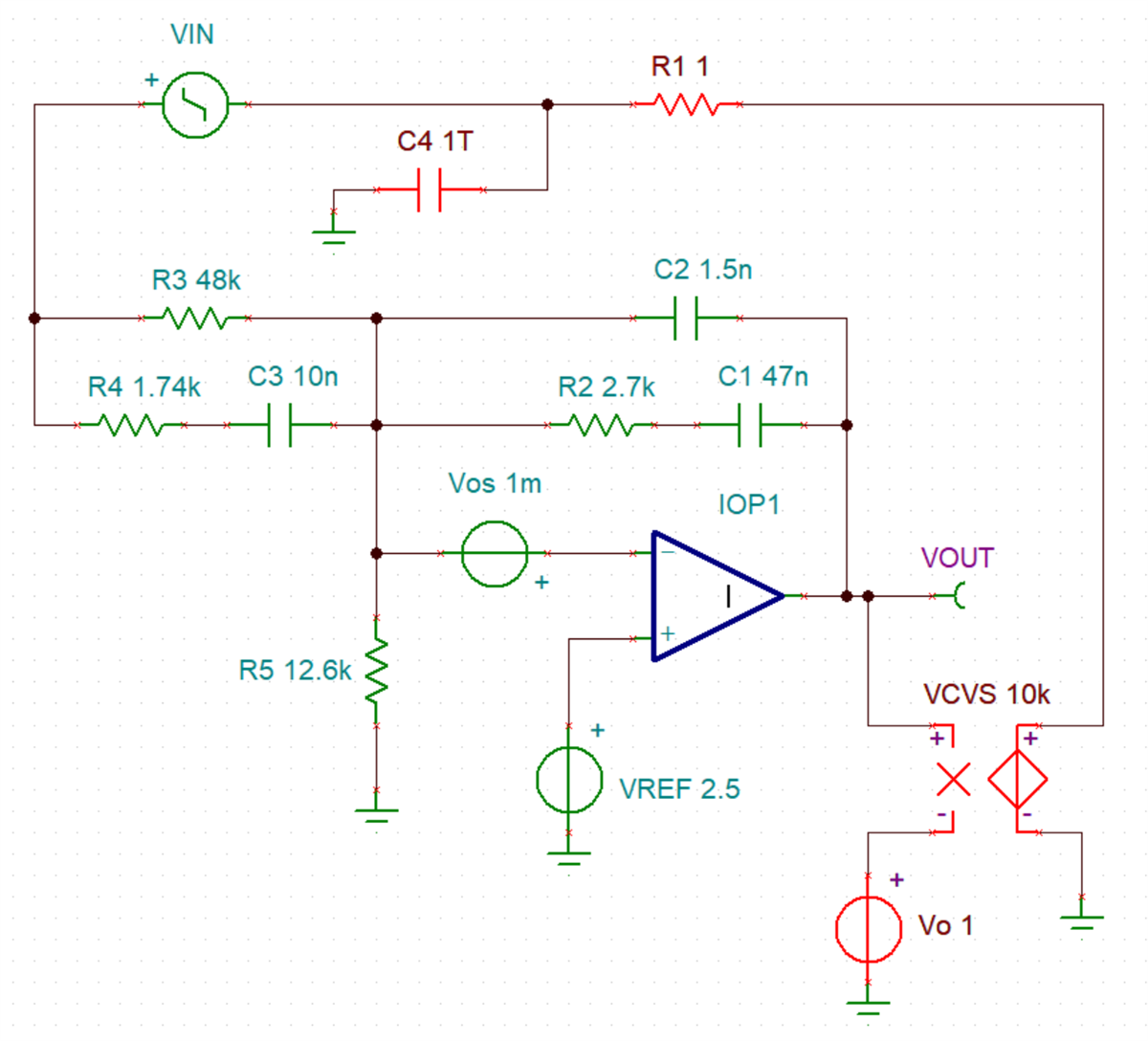
  • It is possible to look at the full forward gain directly by DC closing the big loop. This also works if the op amp is real and has offset voltage and VOL,VOH limitations. Vo sets the op amp DC output voltage. 

    8875.type3compensator.TSC

  • Former Member
    0 Former Member in reply to user6349971

    Hi User,

    Can you please provide the circuit you used?  I do not understand your question as is.

    Thank you,

    Daniel

  • I can't understand this circuit work. what is the red element  doing

  • User,

    The VCVS amplifies the difference between the output and a 1V source by 10,000 (number not important). The output of VCVS feeds your circuit that wants 12V as an input. So your circuit will output 1V + 12V / 10,000 = 1.0012V. Once again exact number is not important. The key idea is that your circuit is biased to a known linear operating point.

    The R and C are a low pass filter set to 1/6.28/R/C which is 1.6*10^-16 Hz which will squash the circuit gain plus the 10k gain even at low frequency, like 1Hz. R can be replaced with an inductor. Therefore VOUT / VIN will be the gain of your circuit as if the red items were not there.

  • I understand the circuit work

    but why I need the red element if I want get the gain the Vout / Vin is OK?
    why need the feedback and RC filter

  • Former Member
    0 Former Member in reply to user6349971

    I believe Ron's intention was to use the large capacitor (C4) to short all AC signals to GND.  He is only interested in passing the DC signal.  Again, this was only to measure the gain.

    Regards,

    Daniel