A related question is a question created from another question. When the related question is created, it will be automatically linked to the original question.
If you have a related question, please click the "Ask a related question" button in the top right corner. The newly created question will be automatically linked to this question.
Please find the below info. i am looking for LVDS output from both the channels.
1. Vcci = 5 V, Vcco = 2.5 V
2. Vh = 2.55 V, Vl = 2.45 V and
3. Vinpk-pk = 200 mv with 2.5 V off set -
4. trainagular with 200 MHz frequency.
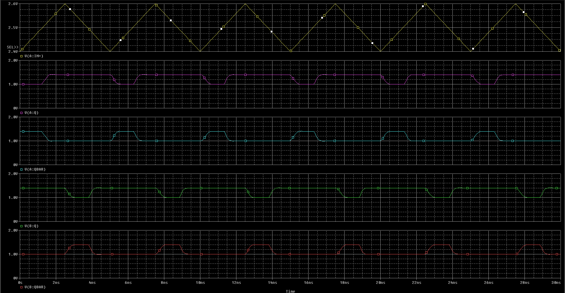
The input signal is sensed volatge signal from power supply of 48 V switching at 25 MHz frequency. I am expecting my outputs as shown below. Please let me know if you need more info.
As depicted by the schematic, I used Channel A on the device in a non-inverting input configuration for your lower threshold (VL). I used channel B in an inverting input configuration for the high voltage threshold (VH=2.55V). The table below depicts the input/output behavior I implemented.
INPUT Voltage Value
Channel A Output
Channel B output
Vin<VL
LOW
HIGH
VL<Vin<VH
HIGH
HIGH
Vin>VH
HIGH
LOW
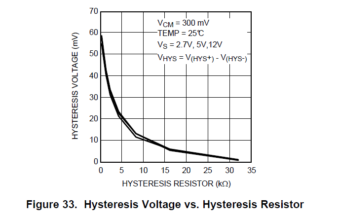
The outputs are correctly in the LVDS output range (1.0V to 1.4V) and I have implemented minor hysteresis (20mV) using R5 and R6 corresponding to the plot I included from the datasheet.
You can omit R5 and R6 to have no hysteresis. Please reach out if you think the simulation needs tweaking and/or if you would like me to change the design parameters.
Thank you for the results and these are very helpful. May I know the name of simlation tool that was used for this design and can I get the simulation files to try for our design.
Also, the input signal is a 25 V sqaure wave and we are trying to use a 10:1 (10 k : 1k) potential divder network to sense the voltage and apply to the comaparator input. May I know if this has any effect on the LMH7322 input side?
I will inquire about ways that you can simulate the circuit and get back to you by end of business day tomorrow (9/23). As long as the voltage seen by the input pins is within the operating voltage range of Vee-0.2V to Vcci-0.5V, then the divider circuit should have little to no impact. By the end of tomorrow, I will confirm if the voltage divider does not impact the circuit. I will also try to find out a way to get you simulating!
As long as the voltage divider network keeps the voltage within the operating range for the LMH7322, the comparator will have no impact. The only concern I would have is filtering your input signal when using a resistor (with inherent parasitics) network. I would make sure your signal out of the divider is as expected.
I have attached the PSpice for TI file that we used below. I believe the simulation is PSpice compatible. Click on the hyperlink if you need to download PSpice for TI. If you encounter any issues with the simulation or have any further questions, let me know.
I am assuming that I have answered your questions so I will close this thread. If you have further questions, please reply to this thread or open another one.
Thank you so much for the simulation tools and file. May I know if I can connect the LE and VEE pins to GND.
Also, in order to filter out the input signal noise, I am thinking of using a small filter capacitor (pF) in parallel with the 0402 sense resistor. 0402 will have little parasitics. But adding a filer cap is going to effect my primary ciruit performance due to the rectangular pulse nature. Could you please suggest if I can go ahead with sense resitor (0402) n/w alone. Any suggestions on this are apprciated.
On page 15 of the datasheet, it states that the LE-not pin should be connected to Vcco pin via a 10 kΩ resistor and the LE pin should be connected to Vee via a 10 kΩ resistor. So to answer your question, you can connect Vee to ground but you should place a 10 kΩ resistor between Vee and the LE pin if you are not using the latch functionality.
As far as filtering your input signal, I would just make sure you are aware of the corner frequency of the low-pass filter that your resistive network (with parasitics) would create. Your input signal would turn into a rounded pulse and lose its high frequency components. Are you trying to sense your input only with passive components?
Thanks for the clarification about the GND connection.
At the moment, we are thinking of passive components as we can't afford much delay. But we are also looking at highspeed active sensing techniques. If there any op-amps available we are ready to use them in our design. Could you suggest any high bandwith active sensing methods using TI opamps.
I am going to forward this thread to the High Speed Amplifiers group to see if they can find a product for your application. Using an active, high speed component to attenuate the input signal will hopefully mitigate filtering of the input (when compared to a resistive network). I hope you get a solution soon.
Just want to confirm I've correctly understood the previous conversation before looking into an amplifier:
You need to attenuate 200MHz 25V square wave. What is the rise time of your input? What is the offset of this signal?
The noise from your voltage divider is too large and so you added capacitance in the pF range to help filter.
I'm guessing you can't reduce voltage divider resistances further due to power consumption?
If my understanding for the above are correct, then we can use an amplifier in a unity-gain configuration to isolate the resistance of your voltage divider and create your low-pass filter at the output of the amplifier before going into the comparator.
Please help provide any amplifier requirements/preferences to help narrow down your search. What supplies are available here? Do you have power consumption, noise, cost, dc precision requirements? Please let me know of any other requirements you may have.
I would like to attenute the following set up. Please see the below figure. The two square wave voltage signals (25 MHz) would be sensed at the two terminals of a Flying capacitor. We want to attenuate the difference of these two signals ( = the voltage across the 4 uF flying cpacitor is 25 V) by a factor of 5. I am thinking of using 2k : 8k potential divider network to achive this. Your suggestions on this will be appreciated
1. Rise time is 0.3 - 1 ns. the offsets are shown in figure.
2. I want to add a pF capcitors to filter the noise in case of resitive divider network. But would like to know high bandwidth (30 MHz) active sensing options.
3. We would like to have as much less power consumtion as possible for this sensing circuitry.
4. Also the delay introduced by the active sensing circuit should be less than 30 ns if possible.
We would like to have a band width of atleast 30 MHz for the active sensing. I guess a diferential amplifier is good candidate but, if you can provide suitable suggestions that would be great. 12 V, 5 V and 3.3 V power supplies are availble. The sensed output signal should be noise free of high frequency components (> 30 MHz) and with the least possible voltage ripple (< 10 mV). At this point we are not worried about the cost.
Please let me know if any more information is required.
Rather than bandwidth, the main limitation here seems to the potential slew rate that you will require. Even at 1ns, the rate of your input will be 25,000 V/us which is beyond the capability of even current-feedback amps. So what is the maximum rise/fall time that you are willing to introduce to your 5V output? or is the only requirement here that the delay must be under 30ns?
That's correct. We aren't much bothered about the input square waves rise/fall times, because our focus is on the differnece between the two signals which is going to be a constant 25 V with certain amount of ripple (100 -500 mV). Also, the ripple frequency is 25 MHz. As long as we are able to capture the 25 MHz ripple, we are good. Yes, we want to have a delay of < 30 ns.
The attached diff amp configuration should be able to meet your requirements. The THS4631 is the only FET-input amplifier that can achieve the slew rate requirements that you require. Please let me know if you have any questions.
Thank you so much for your suggestion. I am planning to use 1 pF in parallel with the two 1.65 K resistors to filter out the noise and for stability. May I have your comments about its' effect on bandwidth of the design. Does it have any consequences on sensing of 25 MHz ripple voltage. Please advice.
I agree this would be helpful both from a noise & stability perspective. Your - 3db bandwidth looks to be 34.7MHz now so you can reduce the cutoff frequency of the low-pass filter at the output as needed.