This thread has been locked.
If you have a related question, please click the "Ask a related question" button in the top right corner. The newly created question will be automatically linked to this question.
Hi,
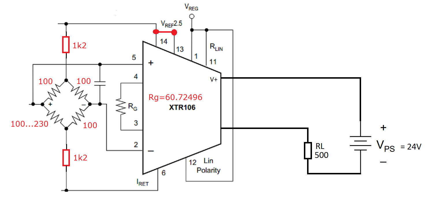
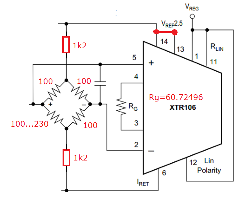
I want to use the XTR106 to create a 4-20mA signal but the signal on Iout is always 24mA.
I use RL = 500ohms and V+=24V.
I try too change the resistances values (Rg and in the bridge) but the oupt is still 24mA.
Thanks you for your help
Arthur
Hi Arthur,
Do you have a full schematic to share so I can verify all of your connections?
Are you grounding the IRET pin? The IRET pin needs to float with respect to the Vloop ground.
Are Vref or Vreg supplying anything else in your circuit? The XTR106 won't be able to output currents smaller than the current draw from the Vref and Vreg pins.
Best,
Katlynne Jones
Hi Arthur,
Are you including the external transistor Q1 as shown in figure 1 of the datasheet. Q1 conducts the majority of the loop current and isolated the majority of the power dissipation from the XTR106.
If you choose not to use the external transistor, which is recommended to maintain the accuracy of the XTR106, it is recommended to add a resistor between pin 8 and pin6.
Best,
Katlynne Jones
Hi Arthur,
what bridge resistors are you using?
Please show us your schematic.
Kai
Hi Arthur,
It looks like you are using the incorrect type of output transistor. Datasheet uses an NPN and your diagram shows a PNP. It would also be helpful to know the part number of the external transistor you are using so we can verify that it will work for this application.
Your schematic is missing the 10nF-30nF recommended supply bypass capacitor connected between V+ and Io. It is also recommended to add a zener diode between V+ and Io for over-voltage surge protection (shown in figure 6 of the datasheet).
Can you measure the voltage across the Vin+ and Vin- pins when you see Iout= 24mA.
Can you verify the reference voltage is 2.5V by measuring the voltage across pins 13,14 and Iret.
Thank you,
Katlynne Jones
Hi Arthur,
additionally to what Katlynne said, try to vary the resistance from 82Ohm to 240Ohm and not from 100Ohm to 230Ohm. And use 1% toleranced resistors for all the bridge forming resistors. Then you should see a change of output current.
Kai