This thread has been locked.

If you have a related question, please click the "Ask a related question" button in the top right corner. The newly created question will be automatically linked to this question.

INA240-Q1: INA240A2 Reference volt shift While applying Load current

Part Number: INA240-Q1
Other Parts Discussed in Thread: INA240

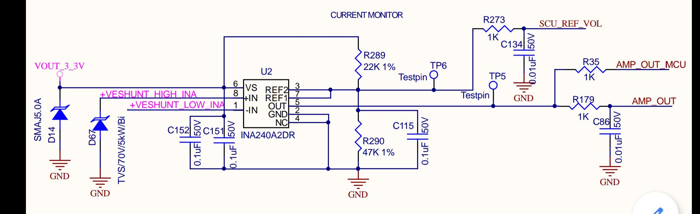
LS Shunt amp(20mR shunt). Opearting supply 3v3. 
  Vin Iin Shunt volt drop Vref Amp_Out
No load 47.5V 0A 0mV 2.193 2.18
90R Load 47.5V 0.51A 10mV 2.185 1.667

during load of 0.5amps .. observed reference voltage shifting by 8mV. 

please let us know the reason for this shift ??

  • Hi,

    If you’re attaching a schematic, it didn’t come through.

    A schematic is necessary to understand the problem statement.

    Regards, Guang

  • Hi Guang, 

    Thanks for quick response. 

    I attached schematic in my first thread. 

    Looks like it missed. 

    Attached here again. 

  • Hi R Reddy,

    The reason for the shift is most likely due to the relatively large values of R289/290. If you make each 10x smaller you’ll see the shift decreases accordingly.

    To remove the shift completely, you would insert a buffer between INA240 and the divider, or replace the divider with a reference voltage IC.

    Regards, Guang

  • Hi Guang,

    You are absolutely correct .. I Tested With 0.1 times the existing values before i wrote to you and found to be working fine. In place of 8mV error i observed 1mV. But I cant go with that solution as its prone to more leakage. We targeted our product to run at low cost and low power ( Buffer and reference voltage also was not considered because of this reason)

    Is it possible to calculate the error  for the given(any chosen) divider resistor values?? If Yes, Pls let me know how .. so that i can calculate worst case error and think of mitigating 

  • Hi R Reddy,

    You’re right about the tradeoffs. Unfortunately the divider approach, although affordable, is trickier to deal with.

    It is possible to estimate the error caused by the divider, the first order error equation in percentage is approximately (R289//R290)/500*100 where R289/290 are in KOhms.

    Due to device variation and resistor tolerance/mismatch, the actual %error will have some deviation from predicted.   

    Regards, Guang

  • Hi Guang..

    We have seen 2 errors here because of divider circuit as reference volt to INA240A2.

    1. Shift in reference voltage at No load (ERROR1)

           with R289 (22k,1%), R290(47k,1%) we should get 3.3V*47K/(22K+47K)=2.244V. But we were getting 2.193V. Which is 51mV Error.

           With R289 (2K2,1%), R290(4K7,1%) we should get 3.3V*4K7/(2K2+4K7)=2.244V. But we were getting 2.240V.  Which is 4mV Error. Negligible.

           Its constant for a given divider resistors. It could be due to the internal resistors of op amp. i would like to know how to calculate this error ?? 

    2. Shift in reference voltage during load (ERROR2)

           with R289 (22k,1%), R290(47k,1%) + 10mV Load we were getting 2.185V . By Which Error is 8mV .

           with R289 (2k2,1%), R290(4k7,1%) + 10mV Load we were getting 2.139V . By Which Error is 1mV Only(Negligible) .

           Its Proportional to the differential input voltage(Load).  i would like to know how to calculate this error ?? 

    INA240A2 at 3V3 Supply No Load With 10mV(20mR Shunt) Load
    Divider Ideal Ref Volt Actual Ref Volt Error1 Actual Ref Volt Error2
    47K,22K 2.244 2.193 0.051 2.185 0.008
    4K7,2K2 2.244 2.24 0.004 2.239 0.001
  • Hi R Reddy,

    An equation can be provided to estimate INA240A2 Vref in this configuration. However due to component variations, deviation from nominal will be hard to control. The equation may not be of much practical usefulness where reasonable accuracy is demanded the divider is made of large value resistors.

    For the sake of system error, the correct approach is to use small dividers in order to minimize the impact of component variation.

    But in any case, here it is, ignoring R273 and anything follows it:

    Vref=(K*Vs – 10*Vshunt)*(R289//R290)/( (R289//R290)+Rint) + Vs*(R290//Rint)/(R290//Rint+R289)

    K=~0.5 nominal; Vs=supply voltage; Vshunt=input differential voltage; Rint=700KOhm nominal internal effective resistance, 15% variation.

    After plugging in numbers, I found your results are largely in range but a little far from nominal values. There might be additional loading by R273 and following circuitry. If so, disconnecting R273 should make the numbers somewhat better.

    Regards, Guang