This thread has been locked.

If you have a related question, please click the "Ask a related question" button in the top right corner. The newly created question will be automatically linked to this question.

PGA309: Calibrating real world sensor,

Part Number: PGA309
Other Parts Discussed in Thread: , MULTI-CAL-SYSTEM

Hi there,

I asked a question a few weeks ago regarding the PGA309 calibration spreadsheet for the obsolete version of PGA309EVM software. It's been closed but I wanted to follow up on it as I still haven't determined the best path forward. 

https://e2e.ti.com/support/amplifiers/f/14/t/943207

Our current process is to mate the physical pressure sensor with the PGA309 electronics (and serial 4k EEPROM), collect pressure and temperature excursion data from the sensor, and do some conversions with the old spreadsheet provided to program the EEPROM through the PGA309EVM software (old version, referenced in previous question).

We want to move to the newer version of the software. If I am collecting pressure and temp data, would it make sense to type (preferably script?) that data to the input fields of the "calibration info" of the "Auto-Cal" tab, and use that to program the PGA309? I guess my confusion is that we take data by our own means, and I'm unsure of the best way to calibrate from here.

Any help would be appreciated!

Thank you

Torin

  • Hi Torin,

    The PGA309EVM-USB allows the calibration of physical real sensors, interfacing the physical sensor with the PGA309 electronics. The Auto Cal routine allows you to perform the PGA309+Sensor measurement of the minimum and maximum pressures at different temperatures to perform the calibration.  A similar solution is the MULTI-CAL-SYSTEM, it allows the connection of multiple customized PGA309 test cards at the same time, and allows the calibration of multiple PGA309+sensor across temperature. The software is very similar to the basic PGA309EVM-USB.  The measurements can be made through the built-in USB-DAQ controller ADC or ext. DMM meter.

    The EVM hardware allows the user the options to demonstrate the calibration process with a sensor emulator or connecting a real physical sensor. The position of jumpers JMP7, JMP4, JMP5, and JMP6 allow users to select either the onboard sensor emulator or an external sensor. JMP12 allows users to choose between VS or VEXC for the sensor power. Screw terminal connector T1 provides the power connection for an external bridge sensor. Screw terminal connector T4 allows connections to each input of the external bridge sensor. Connector T5 allows connection of the external temperature sensor.

    By navigating to the “Set Up Cal” tab, the user can Customize the calibration targets and settings. Section 4.10 of the PGA309EVM-USB user's Guide  discusses this process.

    -          The user can press the Create Model File button to edit a model file or create a new model file, button.  Figure 22 of the PGA309EVM-USB user's Guide shows the Create Model window that opens when the Create Model File button is pressed. If you unselect the “Use sensor Emulator” field, you can use a real physical sensor, and select a “Pre Cal File”. These settings are saved in the Model_Files

    -          Similarly to the legacy excel calculator, the “Create Pre Cal file” allows you to select the different settings such as the PGA309 voltage supply, Vref ext. or Vref int, the fault configuration, Over scale/under scale limits, mode (4-wire Vout, 3-wire Vout or current out), Enable Vexc, the number of temperatures used in the calibration routine. The settings above are saved in the “Pre_Cal File”.

    To answer your question, the customized settings for the calibration routine are configured on the “Set Up Cal” tab, and saved on the “Model file” and “Pre Cal file”. The Auto Cal tab only displays the measurement results as they occur, and the GUI does not allow the calibration measurements to be over written.

    When you say you take data by your own means, would the MULTI-CAL-SYSTEM work for you, where you can connect your Custom PGA309 +EEPROM+ sensor PCB board to the hardware and run the calibration?   In general, it is easier to become familiar with the PGA309EVM-USB before using the MULTI-CAL-SYSTEM.  Another option is to modify the PGA309EVM-USB hardware to interface with your own card. Please describe in more detail what you mean when you take data by your own means.  Is the actual measurement not using the legacy EVM hardware?  

    One difference between the old system is the iterative calibration algorithm of the PGA309EVM-USB or MULTI-CAL system results in better post-calibrated accuracy. 

    Thank you and Regards,

    Luis

  • Thank you Luis, your information has been extremely helpful. 

    When we collect pressure and temperature data from the unit, it is not connected to the PGA309EVM-USB. We have an automated system that we use to collect sensor data as a text file at user specified temperatures/pressures. The PGA309+EEPROM circuitry is attached to the sensor when we do this, but it is not programmed (we follow the same process for units that are not PGA's).

    My confusion might be that we are likely not using the PGA309EVM-USB as intended. We collect text files from a large batch of our bridge sensors+PGA309+(unprogrammed EEPROM's) while in an environmental chamber, and program the Zero dac and Gain dac to the PGA309 after we collect the data. We do this using the old spreadsheet provided with the previous version of the software, using the OWP via a single connection to TP26, and the circuit ground is tied in to the unused GND of JUMP8. We are using the 3-wire output mode. (No USB DAQ Connected)

    This issue is popping up because the macro's of the excel sheet we've been using is not working with our necessary update to windows 10.

    I believe the multi-cal system is the direction we would like to take this, but my current focus is determining how to update our current process with the new software. 

    I'm wondering if I can convert the text file we collect into a "sensor emulator" file for each sensor, and use that to calibrate/program the PGA309 EEPROM using the EVM? Since we do a high volume of these units, it would not be feasible to run a full pressure and temp calibration on each individual unit currently (but I will be looking into updating to the multi cal tool).

    I guess this has given me more clarity on what my question actually is:

    What would be the best way to take a text file of sensor data collected externally (without EVM), and use that to program the eeprom of our PGA309 with the current version of the software?

    Could I need to create a sensor emulator file for each sensor, and run the auotcal sequence using that? Or maybe do some conversions on our collected data and program the eeprom directly?

    Thank you again for your time Luis, I'm a newer engineer so I apologize if any of my questions are redundant. :)

  • Torin Vanderpool said:

    We do this using the old spreadsheet provided with the previous version of the software, using the OWP via a single connection to TP26, and the circuit ground is tied in to the unused GND of JUMP8. We are using the 3-wire output mode. (No USB DAQ Connected)

    I apologize, I'm making this harder by giving incorrect information. We are using the USB Daq platform, but we do not have the PGA309 test board attached.

    Thank you

  • Hi Torin,

    Since you take the data of the sensor+PGA309 using a separate hardware setup, your best option is to calculate externally the correct Zero dac and Gain dac settings (and all register settings) to program the PGA309 EEPROM similarly as you have done in the past.  

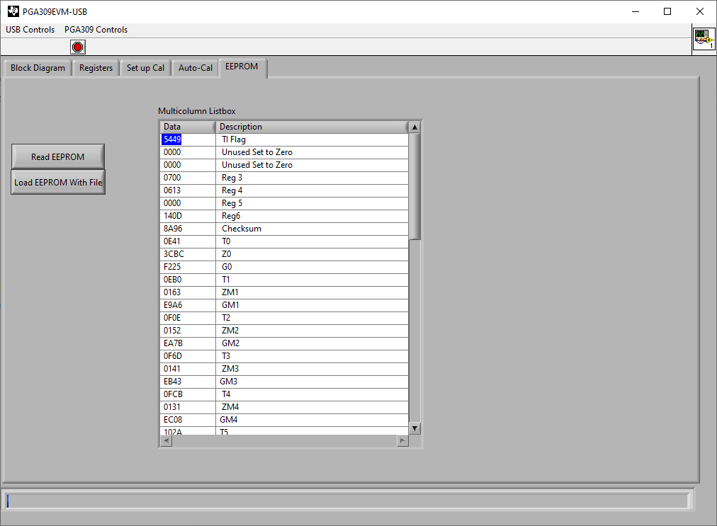
    The PGA309EVM-USB allows the direct read/write programming of the EEPROM on the 'EEPROM' tab. The EEPROM tab allows you to load a text file that contains the custom EEPROM settings.  From your calculated register calibration values, you could generate a text file with the calculated register values and program the EEPROM directly.    

    On the PGA309EVM-USB the PGA309 calibration programming occurs primarily through the ONE-wire PRG pin during the calibration routine, however the 'EEPROM" tab allows the direct read/write EEPROM programming via the 2-wire EEPROM I2C interface. The GUI allows you to load an external text file with the EEPROM register settings.

    Please ensure to program the correct TI flag, and write the correct values for the Checksum1 and Checksum2 register settings after updating the Zero DAC, Gain DAC or after updating any of the register settings.  Attached is a snapshot of the EEPROM tab.  The text file contains the EEPROM register contents after the 8th row (after the row [EEPROM]), in the same order as displayed in the GUI panel description.  The register contents on the EEPROM text file are stored in decimal value.   However, on the GUI display, the equivalent register value displays in Hex format.  

    Thank you and Regards,

    Luis

  • Thank you for this information Luis. I appreciate your time, this has been very helpful.

  • Hi Torin,

    Thank you, let us know if you have questions.

    Kind Regards,

    Luis