This thread has been locked.

If you have a related question, please click the "Ask a related question" button in the top right corner. The newly created question will be automatically linked to this question.

XTR111: XTR111 ERRORS IN CURRENT VALUES

Part Number: XTR111

HI,

I AM USING A CURRENT LOOP TRANSMITTER CIRCUIT FROM THE DATASHEET OF XTR111, THE INPUT TO THE XTR IS 0-5V COMING OUT OF A SENSOR'S SUPPORTING CIRCUITARY. WHEN I USE THE SENSOR IN THE VOLTAGE MODE, IT SHOWS THE CORRECT READINGS (MY CIRCUIT HAS JUMPER OPTION FOR SELECTING CURRENT OUTPUT OR VOLTAGE OUTPUT) WHICH I HAD VERIFIED WITH ANOTHER STANDARD METER. WHEN I USE IT IN CURRENT LOOP MODE, INSTEAD OF 4.3mA(WHICH SHOULD BE THE ACTUAL READING) IT SHOWS 6.5A !!

THE SIGNAL COMING OUT OF MY SENSOR IS A PWM SIGNAL WHICH I HAD CONVERTED IT IN 0-5V USING MANUFACTURERS DATASHEET GUIDELINES AND IS TESTED AND FOUND OK.

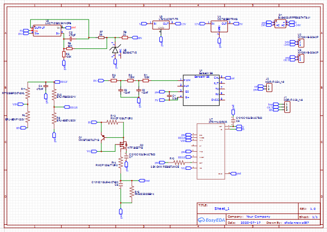
CAN YOU PLEASE LET ME KNOW WHAT MISTAKE I HAD MADE. I HAD ATTACHED MY SCHEMATIC TO THIS POST FOR YOUR REFERENCE.

WAITING FOR YOUR REPLY.

THANKS..

  • Hi Chetan,

    unfortunately, it's impossible for me to decipher your schematic :-)

    Can you please post again?

    Kai

  • HI KAI..

    THANKS FOR PROMPT REPLY.

    SORRY, I MADE IT DIFFICULT TO UNDERSTAND.:-)

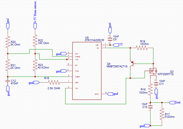
    ATTACHED IS THE SCHEMATIC.

    I DID AN EXPERIMENT, I REMOVED R17 AND THE OUTPUT WAS 4.3mA NOW, WHICH WAS 6.5mA EARLIER.

    PLEASE GIVE YOUR SUGGESTIONS. DO I REALLY NEED R17?? AND IS ANYTHING WRONG IN THE CIRCUIT??

    ,

  • Hi Chetan,

    can you also show the jumper section?

    The output signal of XTR111 is a current which flows out of the drain of Q3. To convert this current into a voltage you need a suited resistor, for instance R17.

    Another issue is R22. R22 needs to be driven very low ohmically. If, on the other hand, there's some relevant resistance in series to R22, the output current of XTR111 will become wrong. Can you also show the circuitry which drives R22?

    Kai

  • HI KAI,

    THANKS AGAIN FOR THE INFORMATION YOU SHARED,

    R22 AND R23 ARE FOR CONVERTING 0-5V TO 1-5V FOR GETTING 4-20mA INSTEAD OF 0-20mA (AS SPECIFIED IN DATASHEET). IF LOWER VALUES IS REQUIRED I WILL DESIGN VOLTAGE DIVIDER WITH LOWER RESISTANCE VALUES.

    I AM GETTING VOLTAGE OUTPUT FROM THE OTHER CIRCUIT AND NOT USING R17 FOR THE SAME.. I HOPE YOU ARE GETTING IT?

    I WILL UPLOAD THE JUMPER SECTION.

    THANKS AND REGARDS

  • Hi Chetan,

    R22 AND R23 ARE FOR CONVERTING 0-5V TO 1-5V FOR GETTING 4-20mA INSTEAD OF 0-20mA (AS SPECIFIED IN DATASHEET). IF LOWER VALUES IS REQUIRED I WILL DESIGN VOLTAGE DIVIDER WITH LOWER RESISTANCE VALUES.

    No need for decreasing R22 and R23. This part is ok. But what is connected to R22? What gives R22 the sensor signal?

    I AM GETTING VOLTAGE OUTPUT FROM THE OTHER CIRCUIT AND NOT USING R17 FOR THE SAME.. I HOPE YOU ARE GETTING IT?

    No, unfortunately not :-) I haven't understood.

    Can you show the full schematic?

    Kai

  • Hi Chetan,

    I agree with Kai that it looks like the PWM filtering you use adds series resistance to R22 which will give you an incorrect current output. It is hard to see the resistor values you are using in your filter from the original schematic, but I don't think that would lead to an output of 6.5A. Can you clarify if you meant 6.5mA or 6.5A? A clear full schematic would be very helpful. You can try to save your schematic as a pdf file and upload using the "Insert File" button.

    Are you saying that you remove R17 to switch from voltage to current mode?

  • hi Katlynne, hello Kai..

    a very thanks to both of you for support.

    yes katlynne you are right, its 6.5mA,, my typing error..

    i had added the schematic  in pdf format, please check it.

    note: when i remove R17, the readings are normal as they should be.. with R17 on board, i guess the current is getting another path to ground and the readings are coming out to be incorrect.

    the jumper j3 selects between voltage output and current output the middle pin is going to the output screw teminal. 1st pin is connected to the sensor voltage output and last pin is connected to the output from the xtr.

    now as per my observation, when R17 is removed my readings are normalized, do i need r17 anyhow?? what can be the consequences of its absence..??

    please guide me..

    Thanks and regards5554.schematic1.pdf

  • Hi Chetan,

    ahhh, a readable schematic! Thank youuuu :-)

    R17 stands for the load (burden) which the XTR111 sees in the following circuit (downstream circuit). Of course, if you have a 500R burden in the downstream circuit which you drive with your XTR111 circuit, you should omit R17. Then your XTR111 circuit will see the 500R burden in the downstream circuit.

    Nothing bad will happen when no burden is connected to the output of your XTR111 circuit. The output voltage simply goes up and saturates. Everything is okay.

    Kai

  • thanks Kai, thanks katlynne...

    i appreciate your efforts..

  • You are welcome :-)

    Kai