Other Parts Discussed in Thread: XTR116, XTR115, XTR111
I've been trying to create two signal converter circuits for Arduino Dues. These circuits would be used to interface the board with 4-20mA enabled industrial devices:
1) Voltage to Current: Since i'm using the DUEs DACs, i should convert 0.55-2.75V to 4-20mA.
2) Current to Voltage: The DUE's input voltage range is 0-3.3V, so, i need to convert 4-20mA to 0-3.3V.
For circuit 2, there is a commercial board called HW-685 that is capable of doing that conversion properly. For circuit 1 I'm trying to develop a solution using a XTR105.I've already assembled the first attempt for circuit 1 and it actually works. I'm able to input 0.55-2.75V from an Arduino Due's DAC port and obtain 4-20mA in the XTR105.
The problem rises when I try to use both circuits at the same time. I still don't have any industrial 4-20mA enabled device here with me now to test so i'm trying to assemble everything and use 2 Arduino Dues to test if every circuit is properly working.
This test circuit is shown in the wiring_v2.pdf file that is attached. The expected behaviour would be:
1) Variable 0.55 - 2.75 V form Arduino Due #1 in its DAC pin is connected to XTR105.
2) XTR105 current loop provides 4-20mA proportional to Arduino Due #1 DAC pin.
3) The current loop is connected to HW-685 current to voltage converter and it provides 0-3.3V proportional to the input current.
4) HW-685 voltage output is fed to Arduino Due #2 and this would be digitally read as a 12 bit resolution 0-4095 signal.
5) A proportional signal to the one coming from HW-685 would be found as an Arduino Due #2 DAC output. This would work as a feedback signal that would be connected to Arduino Due #1 and would provide a way of comparing the consistency of the information that is sent and the one that is read as feedback. If the signals are within a certain expected range, this would mean that every circuit is working fine.
The problem happens when I connect the Arduino Due #2 GND to Arduino Due #1. The current drops at the XTR105 and everything goes wrong.
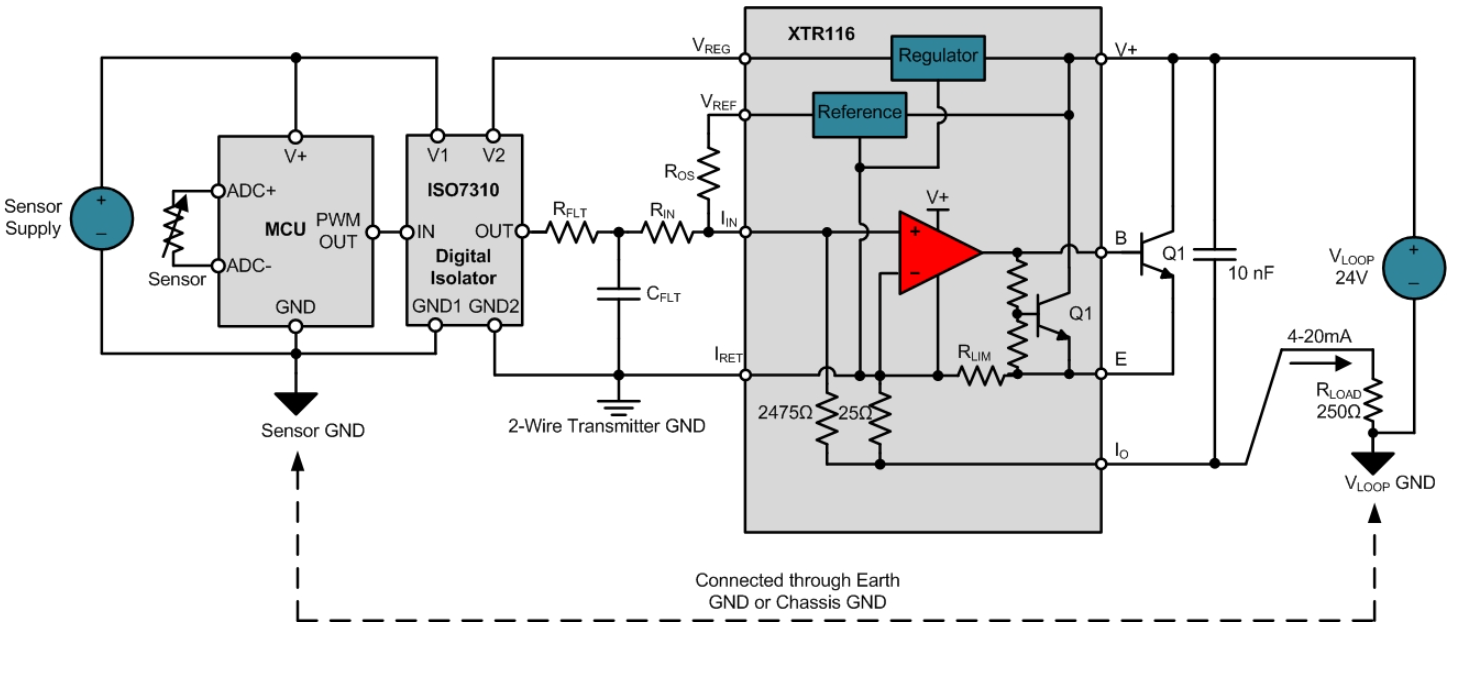
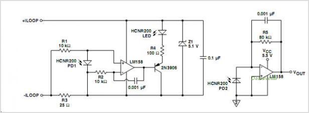
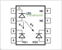
Reading some posts in this forum it seems like I should use an isolator since i'm not powering Due #1 with Vreg pin of XTR105. I just want to confirm if my understanding of this issue is correct or if I'm missing some point. I bought a HCNR201 analog optocoupler and I'm wondering if that would fix the problem or not.
Will I be able to achieve this test circuit if I provide this galvanic isolation between the XTR105 and Arduino Due #1 using a HCNR201 analog optocoupler?wiring_V2.pdf