Other Parts Discussed in Thread: BUF602, , TINA-TI, OPA860
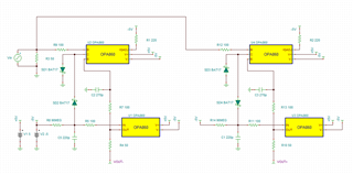
Following the datasheet figure 48 bipolar peak detector circuit using the OPA615 in TINA the negative Vout- doesn't work as expected. The positive Vout+ will track the Vpositive peak but the Vout- vpeak is about 1.8V more negative than the input. If I do two circuits, neither with the buf602, one for Vout+ and one for Vout- and drive them with the same input I get the expect Vpeaks for each circuit difference being the diode direction.
I'd like to capture the Vpeak values of a bipolar signal between -1V to 1V. Has this circuit been modeled in TINA, can a working schematic file be shared to use in the TINA tool?


