Part Number: OPA858
Hello,
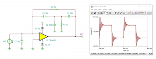
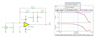
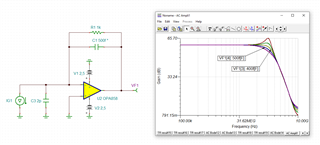
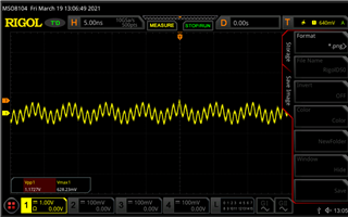
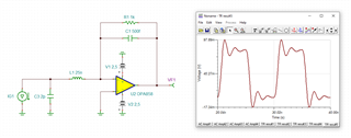
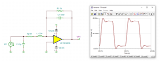
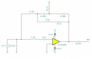
I'm currently testing and designing a transimpedance amplifier (simulation circuit below). I'm running into a few issues right now where when I supply power to the circuit, the output on my oscilloscope oscillates. I figured this was due to my feedback resistance and capacitance not being tuned properly, but I'm using the GBWP calculator that TI references in their TIA design app note for these values.
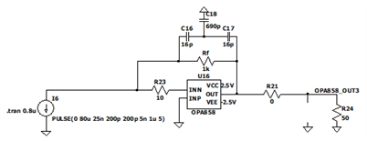
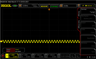
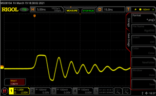
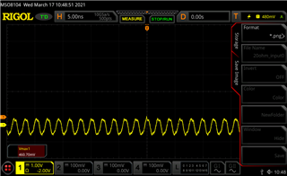
Based on a 1kohm feedback resistance and a 5.5GHz GBWP of the OPA858, my feedback capacitance should be ~0.34pF if my input capacitance is ~2pF. I used a capacitive tee network to get close to that value. Below is a screenshot of what I'm seeing on my scope.
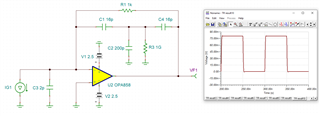
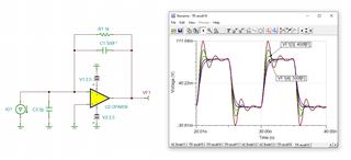
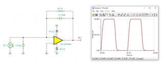
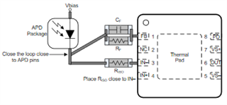
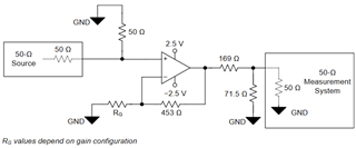
Initially in my design, I placed the 169 and 71.5 ohm resistor (reference below) on my output to match it with the 50 ohm scope, but I noticed my output was being divided so I had that removed.
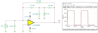
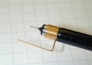
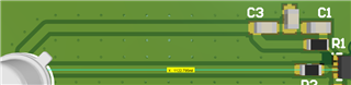
Is my feedback resistance too low? My photodiode is roughly 1 inch away from the OPA858, and I've been playing around with the feedback values, and I can't seem to get the oscillation to go away.
Any help would be appreciated. Thanks!