This thread has been locked.

If you have a related question, please click the "Ask a related question" button in the top right corner. The newly created question will be automatically linked to this question.

OPA858: Photodiode Amplifier for Short (1-2ns) Laser Pulse

Part Number: OPA858
Other Parts Discussed in Thread: TINA-TI, OPA855

Hi,

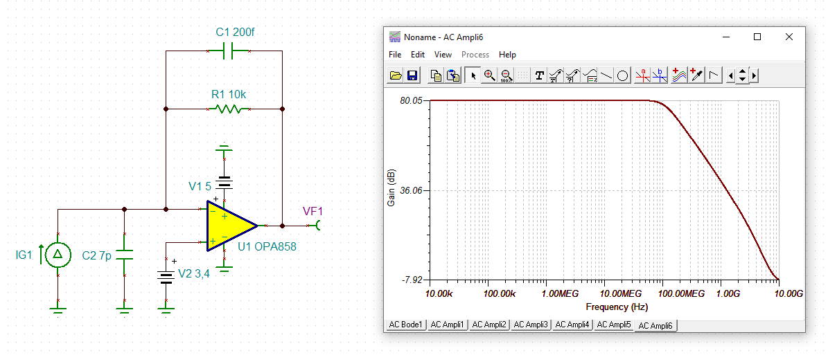
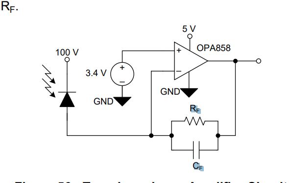
For a project I am working on I need to have a combination of high speed and high gain amplification for a TIA. I have 1-2 nanosecond laser pulses and a photo diode to capture the response. While the pulses are short the pulse frequency is only 200khz. The photodiode I am using is the SAR3000 from Laser components. with 7pF capacitance. I am currently using a OPA858 amplifier in a TIA configuration. I am essentially using this circuit below that was from the OPA858 datasheet. 


My feed back resistor has been anywhere between 1k and >100k. I have been using the closest capacitor that I can find to go with the resistor based of the 0508 TIA Calculator from TIA.

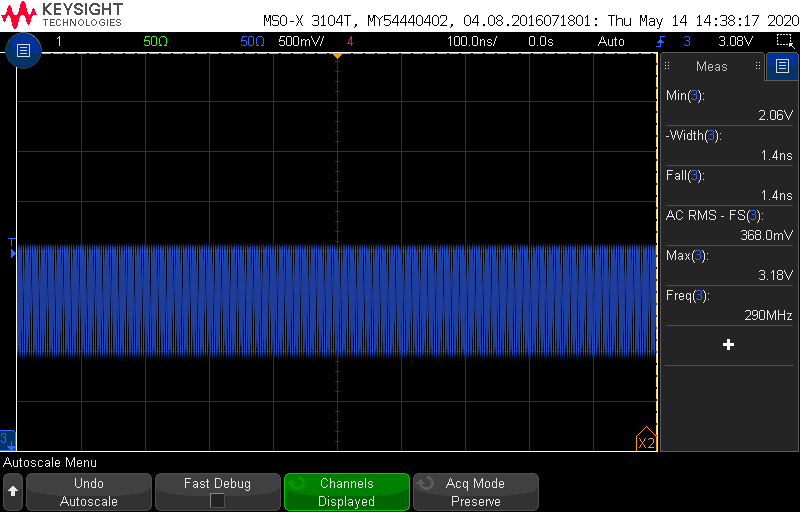
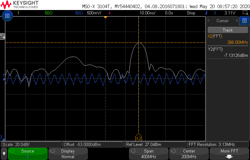
When I try to get high feedback resistor values from the TIA to detect some of the low power current pulses I am not getting the gain that I would expect. I tried the same power level and setup with only a different resistors and got the same peak feedback. 

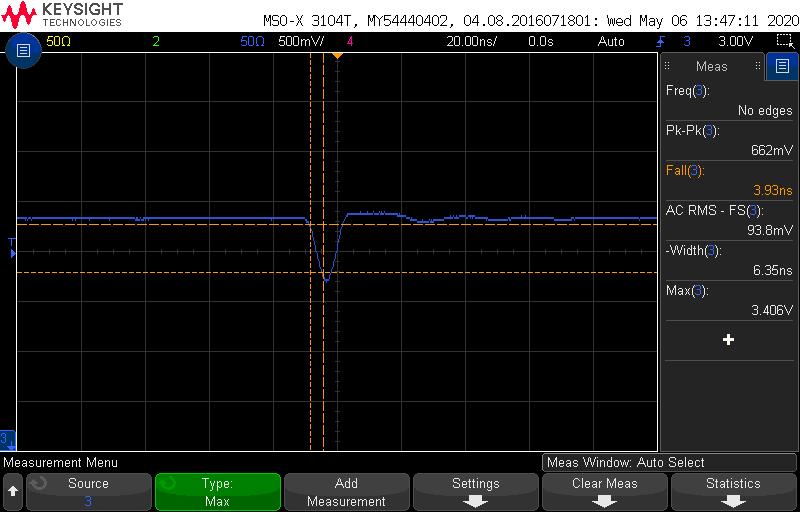
10k feedback resistor 

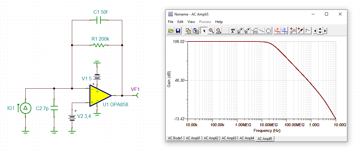
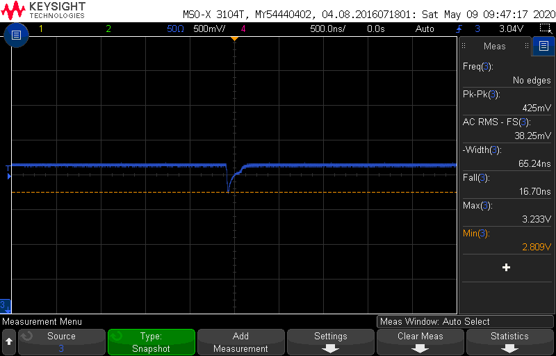
200k feedback resitor


I understand that as I increase my feedback resistor there will be a reduction in bandwidth but I still should have seen a gain in my peak voltage. Any idea why I am seeing this behavior?

Thanks,

Jared


  • Hello Jared, 

    Can you provide the feedback capacitances you used for each configuration?

    Best,

    Hasan Babiker

  • Sure thing.

    1k- 0.68pF

    10k- 0.2pF

    200k - I didnt use a feedback capacitor since there it was calulated out to be <0.05pF.

    From what I understand having values that weren't exactly what they were supposed to be would cause them to have oscillations correct? Would it have any effect on amplitude of the response?

    Thanks,

    Jared

  • Hi Jared,

    these are the TINA-TI simulations:

    jared_opa858.TSC

    Yes, choosing the wrong feedback capacitances can result in wild oscillations :-)

    Kai

  • Hello Jared,

    Your amplitude is being limited by the bandwidth of your circuit, as Kai has shown in the figures of his response. You are correct that the stability of the circuit is related to the capacitances used in the feedback, however in this case your feedback capacitors can be changed both to maintain stability and significantly increase your bandwidth. Here are some suggested values to use that should help increase your bandwidth significantly (calculated for 60 degrees of phase margin):

    1k - 1.3pF

    10k through 100k - 1.85pF

    I've attached the stability analysis of your circuit here, this should help in fine tuning the right feedback capacitance.

    jared_opa858_stability.TSC

    Best,

    Hasan Babiker

  • Hi Hasan,

    I understand what you are saying with the bandwidth limiting the amplitude. To test that out I took a circuit with a 30k feedback resistor and compared the performance of the amplitude between two different capacitance values. 0.2pF and 1.5pF (Closest values I had on hand to match the calculated and your suggested)

    0.2pF above. This saturated the TIA as I would have expected. 

    1.5pF above. This greatly diminished the overall amplitude of the signal and also changed the shape of the pulse significantly.

    From what I understood from your last post this should have increased my bandwidth and while I might have still saturated my TIA I shouldn't have seen the decrease in amplitude like that. Any reason that would explain the behavior that I am seeing?

    Thanks,

    Jared

  • Hello Jared,

    I accidentally confused maximizing the loop gain bandwidth with the bandwidth of the circuit, sorry about the confusion. Actually the calculator you were using is designed for achieving a Q-factor of 0.707 to optimize for the greatest bandwidth without significant overshoot. The only to increase the bandwidth further is by lowering the feedback capacitor and adding more overshoot to your pulse response. As you mentioned before, however, there is a fine point between doing this and having the circuit oscillate completely. 

    In this reference design the Q factor was increased to 0.95 in order to give a greater bandwidth. To calculate for the Feedback capacitance for a certain Q factor you will have to use the equation the calculator is utilizing, found here (equation 12). The F-3dB bandwidth in equation 12 will need to be changed to F0. F0 can be calculated using equation 10 & 11. 

    You will notice that since you already aren't using any feedback capacitance in your 200k gain circuit, lowering it further isn't possible. The only way to achieve a higher bandwidth in this case would be to switch to a faster amplifier (The OPA855 might be a good option if you want to go this route).

    Best,

    Hasan Babiker 

  • Hi Jared,

    another way to increase the bandwidth is to use a detector providing a smaller detector capacitance:

    Kai

  • Thanks for the information. I will try changing values for a higher Q factor. I saw the OPA855 as an option but what concerned me was the input bias current is significantly higher for that model. 

    Since I am trying to read very small fast currents, that would cause a large offset on all my signals. Do I understand this correctly? And if so is there any way to combat this?

    Thanks,

    Jared

  • Hello Jared,

    You are correct in that the bias current of the OPA855 will act as an offset to your signal. If you don't care about your DC signal, one solution would be to AC-couple your output in a following stage.

    Best,

    Hasan Babiker

  • Okay thanks, I would like to keep the full range of the op amp but if I absolutely need more bandwidth that might be an option. 

    Another strange thing that I am seeing with the 30k feedback resistor and 0.1pF feedback capacitor, is some strong oscillations at ~280Mhz. Below is a scope trace of the oscillation.  

    The amplitude of the signal varies depending on the environment. If I move my hand around the board the level and amplitude will change wildly. The frequency though will stay the same. Is it possible that my opamp is unstable? Or could this be due to parasitic capacitance through the board?

    Thanks

    Jared  

  • Hello Jared,

    While I do get that you should have 55 degrees of phase margin when using 30k and 0.1pF, this circuit is very sensitive to parasitics and component tolerances. Your feedback capacitance would only need to be lowered by 0.025pF to reach marginal stability, this value would be even smaller if the feedback resistor is also lower than 30k.

    Best,

    Hasan Babiker

  • Hi Jared,

    I think the feedback resistor is too high. With this high feedback resistance it's very tricky to find the proper match of feedback capacitance to detector capacitance and even the least stray capacitance can ruin the performance.

    Please see these posts giving additional tips:

    Kai

  • Thanks for that information.

    I have read through those post and tried a few things. The main thing I attempted was to reduce the feedback resistor down to have a more stable circuit. I have changed the resistor to a 1k value and put a 0.75pF +/- 0.02pF capacitor as the feedback capacitor.  Even with doing both of those changes the frequency of the noise has not changes and the amplitude of the noise has not changed as much as I would expect it to. You can see the 1k Rf test below. 

    The noise gets stronger when exposed to sunlight but actually receiving that light shouldn't be the cause since any sunlight current should just be a constant offset. Is there any other source that could cause that noise? From all the calculations I have done, I should be stable in all of these configurations, and my actual op amp noise should be significantly less that what I am seeing here. 

    Any suggestions would be much appreciated.

    Thanks,

    Jared

  • Hi Jared,

    can you show us a photo of your setup? Do you have a layout you can share with us?

    Kai

  • Hello Jared,

    Can you also provide the rise/fall time of your pulses?

    Best,

    Hasan Babiker

  • Sure thing. I will send it to you as a message. I would prefer not to put the design out publicly on the forum. 

  • Sure thing the rise and fall time of the return pulse is about 2-3ns and the pulse width is around 4-5ns. The laser pulse has a pulse width of around 2ns and with a rise time of 1ish ns. 

  • Hi Jared,

    thanks for sharing the documents.

    You need an isolation resistor in series to the output like shown in the schematic of figure 64 of datasheet:

    Unfortunately, there's a mistake in the layout recommendation of figure 64, which shows the right end of Rs connected to signal ground. This is wrong!!!

    To be able to connect a 50R cable and 50R measuring equipment to the output of OPA858, I would choose Rs = 50R. So, remove your R23 and install a 50R series resistor instead. This should do the trick :-)

    Kai