This thread has been locked.
If you have a related question, please click the "Ask a related question" button in the top right corner. The newly created question will be automatically linked to this question.
Dear Community,
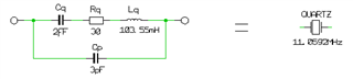
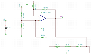
I am looking for developing a clock signal generator (13.56 MHz) circuit using the TL3016 comparator something similar to the LT1016 comparator from Analog devices. Can anyone suggest the reference design to design and simulate with TINA-TI?
Thanks in advance.
Best,
Aaditya
I hope this is ok with you but I will provide the required support in our LMV7219 E2E post instead of responding to both individually.
So I will be closing this post.
Chuck
Dear Chuck,
Could you plz close the previous one and start with this!
Thank you~
Best,
Hello Aditya,
Kai is on the right track, as this is a standard RFID frequency, there are many of-the-shelf oscillator modules available. They would cheaper, smaller, lower power and initially more accurate than a crystal + comparator + discrete components.
If you do wish to "roll-your-own", the LMV7219 datasheet describes the front page crystal circuit in section 8.2.2.4, though I personally think 200 ohms series resistance is a bit low and may overdrive the crystal (maybe around a few k), but not shown is the trimmer caps that may be needed to get the crystal on frequency.
You can also create a simple crystal oscillator with an inverting gate, which may be simpler and cheaper. Just Google "crystal oscillator inverter gate circuit" and you will see plenty of examples (the one with the two caps to GND is recommended...as it is easy to trim if needed)
We even have an application note about inverter crystal oscillators:
Dear Kai and Paul,
Thank you for your kind reply.
By the way, the reason for using a comparator is to generate a stable signal regardless of the driver circuit. I would like to simulate the circuit in TINA-TI for off-the-shelf and using the LMV7219 comparator, however, I am wondering how I can model the crystal oscillator circuit.
I am very grateful for your suggestions and/or recommendations.
Best regards,
Hi Aaditya,
I did this for a 11.0592MHz quartz once:
Apply the Thomson formula to "Cq" and "Lq"
I would decrease "Lq" a bit to give 13.56MHz. I get 68.88mH.
Kai
Thanks Kai for education us all on this. I will definitely be filing this away for future use if needed.
Aaditya
This was an interesting question where I initially thought the same as Kai to buy this off the shelf directly. Thank you for providing the additional context of your question.
Chuck
Dear Kai,
Thank you for your suggestion. However, when I tried to simulate your circuit with the reference model of LMV7219, I could not observe the oscillating signal.
Any comments plz!
Best regards,
Aaditya
please upload your TINA schematic so we are working from the same starting point.
thanks
Chuck
Be sure to select "Zero Initial Values" in the Transient Analysis menu whenever simulating an oscillator, so that the simulator starts from zero volts instead of finding a steady-state DC bias point.
Aaditya
thanks for sharing. Paul and I will consult and get back to you on this.
Chuck
Aaditya
Basically Paul and I had to alter the values of the crystal to get oscillation. Seems like this is very challenging to get the simulator to reach a steady state. Definitely need to run simulation for an extended period of time. Sorry I wasn't able to help more on your circuit.
Chuck