This thread has been locked.
If you have a related question, please click the "Ask a related question" button in the top right corner. The newly created question will be automatically linked to this question.
Hi, I searched about slew rate and settling time in google.
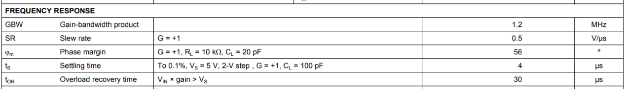
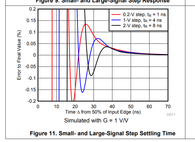
people said that if i want to measure slew rate, i should put large signal input and if i want to measure settling time, i should put small signal input.
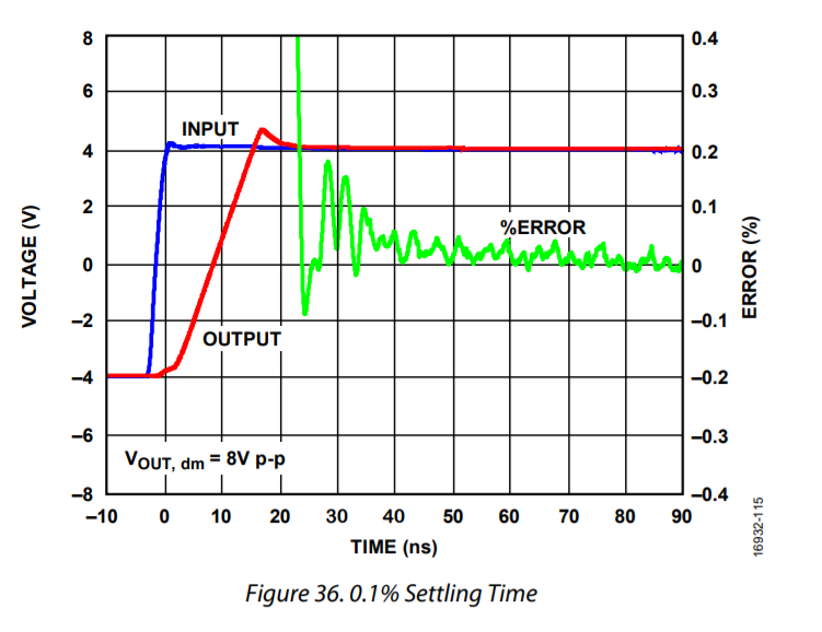
I was confused because if i understood these factors correctly, slew rate is about slop of output voltage tracking input signal voltage and settling time is about the time needed output voltage to get to target voltage from 0.
did i understand these concepts correctly? if i did, why do we differentiate small signal and large signal when measuring these factors?
Hello Yunsik,
Yes this is indeed a difficult topic, especially with many op amp datasheets treating things slightly differently - but,
1. The amplifier at whatever external set up it has will have some small signal AC response shape
2. Be that 1st or 2nd order, an applied step will try to follow the ideal response shape as well as possible on the output
3. 2nd order is more interesting, and it will have a smoothly varying instantaneous dV/dT.
4. if that dV/dT exceeds the device slew rate, the linear response will break off and the output will "slew" at the available slew rate
5. By definition, if the output is in a slew limited transition, the loop is open and you will typically see a single overshoot then recovery to final value - not a linear response at that point.
6. Normally, that slew limited step will have a much longer settling to final value than a step that stays linear.
7. Some amplifiers have different rising and falling edge slew rates, not clear which one is being used in the spec tables sometimes, should use the slowest, but not always the case.
So, Large signal slew limited steps are never used for settling time reporting - although they will certainly have a number, you just can't relate it to the small signal response shape.
One of the more interesting new relationships I worked out a couple of years ago, is that the peak dV/dT on a 2nd order response shape is approximately 2.85*Vstep*F-3dB. You can use this in 2nd order cases to see if your required step size is going to slew limit - probably more than you ever would want to know, but that is all worked out in these two articles - I was mainly after the required slew rate in active filter stages - and this gives it to you nicely,
https://www.edn.com/design/analog/4443250/What-is-op-amp-slew-rate-in-a-slew-enhanced-world--Part-1
https://www.edn.com/design/analog/4443345/What-is-op-amp-slew-rate-in-a-slew-enhanced-world--Part-2
Hi Yunsik,
I recommend watching out TI Precision Lab videos on Slew Rate. The videos discuss Slew Rate and Settling Time and they show that there is a small signal settling response after the op amp stops slewing like Michael mentioned.
Thank you,
Tim Claycomb
Oh and I might add while that simple estimate of what the output signal step would require in a peak dV/dT gives you a minimum for the amplifier being used. Normally I would then guardband that by 2X in picking parts for the application as slew rate does have some variability part to part and over temp.
Hi Yunsik,
an OPAmp is a very complex circuit. It's the result of decades of electronic development. It's not easy to fully understand an OPAmp. And most datasheets only show simplified schematics of the internal circuit. Another approach is to think of an OPAmp as a black box with a very certain behaviour. As an OPAmp is usually the faster the smaller the output signal is, datasheets usually contain two data about speed, the "Settling Time" for very small signals and the "Slew Rate" for very large signals. This is just convention and is historically grown. Another important speed data is the "Maximum Peak Output Voltage vs Frequency".
Kai
Hi Kai,
The Settling Time specified in an op amps datasheet is usually a large signal (10V step, 2V step, etc.) not a small signal response. See below.
Bandwidth can be used to calculate the small signal settling of an op amp. Rise Time = 0.35/Fc where Fc is the cut off frequency (or bandwidth of an op amp).
Thank you,
Tim Claycomb
Well what Tim was saying did kind of point out how confusing this is.
1. That spec snip was not from the LM358B data sheet, but the point was there is (on the slower parts) a settling time where the transition is slew limited
2. If your large signal settling spec is slew limited, can't really use the time constant ideas to relate bandwidth to settling
3. The rise time equation is correct for a 10% to 90% single pole, but again not settling time
4. The settling time to a target window for single pole is a number of time contants. 0.01% is 10 time constants,
The LM358 spec is here,
that is a 0.1% settling to in 4usec on a 2V step (why there is a Cl who knows). can't find that equation right now, but lets say 7 time constants for 0.1% and estimate that as 1/(2pi1.2MHz) = 130nsec. So 7 times that is 928nsec far faster than the reported 4usec. So, it must be slewing . a 2V step with 0.5V/usec is 4usec, so this totally a slew rate set spec in this case, not related to time constants. And probably wrong as the slew rate takes up the whole 4usec but you still need time from there to get into the 0.1% window.
In higher speed parts, when settling time with different step sizes were needed, we would slow the input edge rate to stay out of slew limiting to stay within a linear response type settling time.
Oh, and I just happened to come across a newer plot on this topic that is interesting - every group does this differently, here is a very detailed and interesting plot on a very new FDA from ADI - the ADA4945 that has about 130Mhz SSBW and 600V/usec slew rate lets say - So this is clearly a slew limited output as you can tell by the straight line and single overshoot in the red curve, once the loop starts to close again, you still have a long window to final value in that green curve. So lets say a 7 time constants to 0.1% on 130Mhz or about 9nsec for a linear response - much longer since their input edge rate put this into slew limiting - so 8V step with 600V/usec is about 13nsec - looks a little slower than that, but then you still have to get linear settled to a final value once that red curve star to get back to 4V line that takes quite awhile showing the approx. 35nsec to 0.1% here - which matches the spec line on page 3. I would have slowed the input edge to stay out of slew limiting say to a 15nsec transition - that would have settled much faster than what is shown here. Probably more like 25nsec from the start of input transition (15nsec ramp, 9nsec to 0.1% window).
So here is the plot we put into the similar FDA THS4551, this is simulated and as we use larger steps we slow the input edge down to stay out of a slew limited edge, that is always a good idea for better settling time if you can do it (this is just saying you need check and reduce if necessary the BW of the incoming signal)
If you can stay linear, the settling times to the 0.01% level are the same with step size, these are obviously not 1st order responses and there is low level ringing that is in the actual time response.
I'm sorry for late reply.
it took me some time to understand this.
not completely, but i think i kind of understand why we differentiate it.
Thank you for your elaborate response! I really appreciate it.
Thank you very much
those videos really helped me understand the difference.