This thread has been locked.

If you have a related question, please click the "Ask a related question" button in the top right corner. The newly created question will be automatically linked to this question.

LM318-N: request schematic review

Part Number: LM318-N
Other Parts Discussed in Thread: LM318

Hi,

The schematic below is circuit for a measurement control application, one of my main customers.

It seems blurry because resolution is not good, but please ask for a review.

thanks,

TS

  • TS,

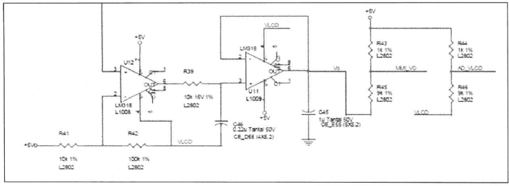
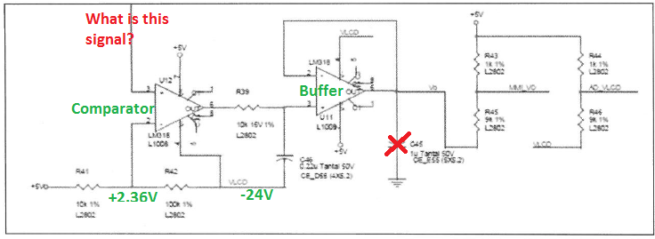
    Is VLCO a negative voltage supply? What voltage?
    Is the first amplifier being used as a comparator?
    The capacitive load on second amplifier might be unstable.
  • TS,

    LM318 is an unusual choice for a new design that doesn't leverage the 3 internal pins for performance tweaking. So I wonder if there may be a better new device.
  • VLCD is negative voltage. -24V.
    And LM318 is used just a buffer, not comparator.
    If TI have another better device for this application, please let me know.
    thanks,
    TS
  • TS,

    I would need to know the input signal to know what op amp would work well.

    The marked out capacitor is bad for stability.

  • Hi Ron,

    thnaks for your help.

    Below is more detail infomations.

    U12, U11 component margin review

    - Proceed with component margin review through waveform measurement in normal circuit.

    1) Waveform measurement and margin check for U12 part

    (RMS, MAX, P-P, MIN is measured value.)

    PIN REF DATASHEET(MAXIMUM) RMS MAX P-P MIN MARGIN VOLTAGE(calculation) Remark
    2 IN- ±15V or midium value of VCC  1.22 3.2 5.3~-24.7 in spec
    3 IN+ ±15V or midium value of VCC 0.833 3.7 5.3~-24.7 in spec
    4 VCC- -20V -24.4V -29.7 in spec
    6 OUT -21.57 5.2 27.9 -22.7 -
    7 VCC+ 20V 5 12.3 in spec

    * Input range calculation

    1) midium value of VCC : -9.7V((-24.4+5)/2)

    2) Maximum range of VCC

    - VCC+ : -9.7 + 20 = 12.3V

    - VCC- : -9.7 - 20 = -29.7V

    3) Maximum range of VIN

    - VIN+ : -9.7 + 15 = 5.3V

    - VIN- : -9.7 - 15 = -24.7V

    Oscilloscpe capture for each pin of U12

    U12 wave.pdf

    2) Waveform measurement and margin check for U11 part

    (RMS, MAX, P-P, MIN is measured value.)

    PIN REF DATASHEET(MAXIMUM) RMS MAX P-P MIN MARGIN VOLTAGE(calculation) Remark
    2 IN- ±15V or midium value of VCC  -20.15 5.3~-24.7 in spec
    3 IN+ ±15V or midium value of VCC -20.18 5.3~-24.7 in spec
    4 VCC- -20V -24.4V -29.7 in spec
    6 OUT -20.15 -
    7 VCC+ 20V 5 12.3 in spec

    * Input range calculation

    1) midium value of VCC : -9.7V((-24.4+5)/2)

    2) Maximum range of VCC

    - VCC+ : -9.7 + 20 = 12.3V

    - VCC- : -9.7 - 20 = -29.7V

    3) Maximum range of VIN

    - VIN+ : -9.7 + 15 = 5.3V

    - VIN- : -9.7 - 15 = -24.7V

    Oscilloscpe capture for each pin of U12

    U11 wave.pdf

    thanks,

    TS

  • TS,

    It looks like the circuit is working well. Do you have any concern about the results?
  • Hi Ron,

    thanks for your answer.

    I have one more simple question regarding the cap you mentioned above.
    On DATASHEET, there is no value for output CAP. How much should I choose?
    Is there any maximum value that TI recommends?

    And if there's any reference schematic for LM318, please share for us.

    thanks,
    TS
  • TS,

    The best capacitance is no capacitance. This is true of almost all op amps.
    If a low pass filter is needed after the op-amp output then use a resistor capacitor filter.

    There is no reference schematic.
  • HI Ronald,

    Perhaps this is my last question regarding this issue,

    As you mentioned in the previous answer, you said that "The best capacitance is no capacitance. This is true of almost all op amps."

    Can you explain this in more detail?

    If you have any material or documents related to this, please share it.

    Any advice is welcome.

    thanks,

    TS

  • TS,

    I suggest the stability section of the precision labs vides for op amps.

  • Hi Ron,
    First, remove the output CAP as you recommend, and OVERSHOOT occured in the output voltage.
    If the CAP is large and there is a risk of component output burnout, we would like to add a current limit resistor of 100K ohms to the output.
    We request your opinion for this.
    thanks,
    TS
  • TS,

    The LM318 does have to charge the capacitor so that does add to load current. How much depends on how much the output moves. Peak current will be set on how fast the output slews.

    100k is fine, if it works. 1K or even 100 ohms should be fine.