This thread has been locked.

If you have a related question, please click the "Ask a related question" button in the top right corner. The newly created question will be automatically linked to this question.

TL082: TL082IDR Failure

Part Number: TL082

Hi All,


 Can you help to analysis a TL082IDR failure?

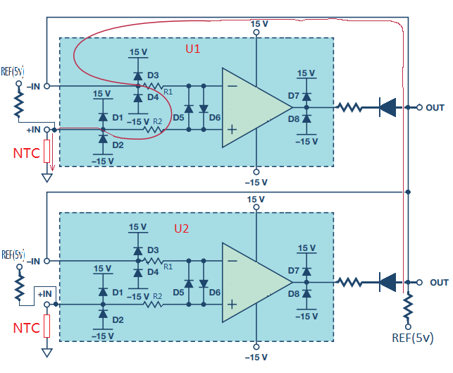
 The schmatic as following: The TL082IDR is used for highest voltage option circuit, these voltages represents different temperatures,these temperatures maybe same or not.Recently a TL082IDR is failure and as tested, find low resistance (132R) between non-inverting input (terminal 3) and negative power supply (terminal 4). Note: NO external FEA surge protection and EMI/RFI filiter part on schmatic. 

 I suspect:

 The Amplifier looks like work as a voltage follower, but actual which is not work as a actual voltage follower. Since the inverting input is feedback the highest input voltage. Only one amplifier is work as a voltage follower, the rest amplifiers will work as comparator, as input voltage cannot keep Vin+=Vin-.

 1. Any issue or concerns for following sch. 

 2. Any issue for TL082IDR in following application, wheather the TL082IDR can be used as a comparator or else issues or concerns?

 3. Others reason caused amplifier failure. Pls correct if anythwhere is wrong or missing. Tks a lot. 

BR,

Xiaobing (Eric)

  • Eric,

    The damage likely entered though the connector as a electrostatic discharge or electrical over stress. The op amp doesn't mind being a comparator but ICC increases by about 1mA per channel when output is VOH.  

  • Ronald,

     Tks for your comments. Questions:

     1. Any terminal protections in the TL082IDR?

     2. How to understand the Vcm value on above circuit? In specfication, the Vcm value should be less than less than (Vcc-)+4V (-11V, -15V+4V) and (Vcc+)-4V (11V, 15V-4V). Especially, during TL082IDR work at comparator conditions. If Vcm voltage level over the spec, what will happen?

     3. How to understand the VId range on above circuit? 

    BR,

    Xiaobing (Eric)

  • Eric,

    1) Section 6.2 in data sheet has ESD ratings. Rating is not high enough for direct human contact. Humans are good at accumulating and delivering high static voltages. For the first four amps add a series resistance to input pin and add a capacitor from input to ground (or VCC-) as a start. Finish with TVS or Shottky dual diode. 

    2) For comparator mode the lowest (least positive) input is the "VICM" if this voltage is lower (more negative) than -11V then input offset voltage degrades. If the voltage is lower than -14V then the output could invert (have the incorrect output state in comparator mode) 

    3) The first four amps see a VICM between ground and Vref.  The last amplifier sees the highest input of the first four and that is divided by 2 resistors before getting to pin 3.

  • Ronald,

     How about internal amplifier? Can you help to confirm following parameters:

     1. Weather the R1/R2 is present?

     2. Weather the D5/D6 is present?

     3. Weather the D1/D2 is present? How about D1/D2 max Blocking Voltage?   


    BR,

    Xiaobing (Eric)

  • Eric,

    TL082 is like this. All of the diodes are parasitic (natural) opposed to ESD specific structures (like D1-D4).

    Diodes block 30V or more  (there is no input to input diode path)