This thread has been locked.

If you have a related question, please click the "Ask a related question" button in the top right corner. The newly created question will be automatically linked to this question.

TAS5760M-Q1: Amplifier internal clock error is latched regardless of i2s clock

Part Number: TAS5760M-Q1

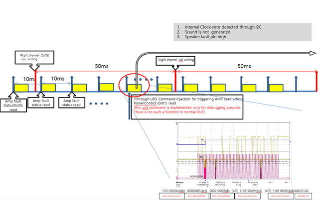
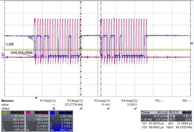
There is a internal clock error happened during the sound generation process.

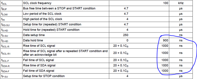
When the issue happened, we tested the I2S clock as below(12K sampling rate is used).:

Test results(Ratio/fs)

LRCK

MCLK

SCLK

fs

Result

Normal  sample without CLKE

12.04399

6163.678

771.231

12


Ratio with Fs

1.003666

513.6398333

64.26925


PASS

Design Ratio(xfs)

1

512

64


Error clock critia -10%

10.8

460.8

57.6


Error clock critia +10%

13.2

563.2

70.4


Abnormal sample with CLKE

12.0439

6156.04

770.9


Ratio with Fs

1.003658

513.0033333

64.24167


PASS

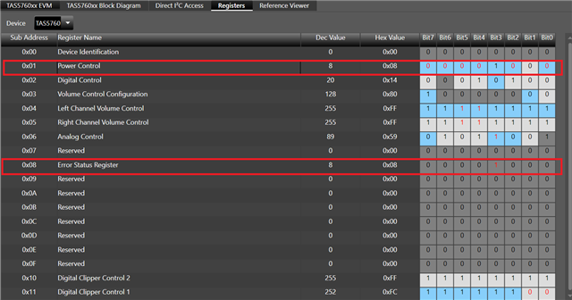
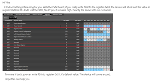
Based on datasheet, the AMP should be recovered, however, the AMP seemed to be stuck after internal clock error happened.

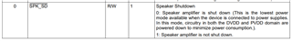
May we know what kind of conditions can trigger AMP stuck in the clock error status. When the clock issue happened, the SPK_SD and SPK_FAULT is high which meant AMP is no issues.

The I2S sound data from MCU is also normal, however, the AMP output is no sound.

  • Hi Yihe

        The device is very sensitive to the Ratio among MCLK, SCLK and LRCK, it is highly recommended to keep the error within ±1. Otherwise the device may not recover from the fault. Please check the clock carefully. 

        Apart from the SPK_FAULT pin, can you use I2C to confirm if there's any fault happens? Please also check if the device has gone into sleep mode when there's no output. Thank you.

  • Thanks for the prompt reply.

    “keep the error within ±1” meant the +1% ? The clock is nearly the same during the normal and after abnormal cases.

    If the AMP is stuck, how to bring back to normal during the sound operation.

    As for the sleep situation, i will check and get back to you.

  • Hi Yihe

        It's not ±1% but literally ±1 for the ratio value.

        If the stuck is caused by the error, toggle the SPK_SD bit to clear the fault if the error condition has been cleared.

        And check the SPK_SLEEP/ADR pin to see if the device is in Sleep mode.

  • the ratio meant the MCLK/LRCK/SCLK to sampling rate, right?

    " toggle the SPK_SD bit to clear the fault if the error condition has been cleared."

    ->It is impossible to do because the error flag is kept to be alive although the clock parts from I2S are stable within specs.

    Are there any solutions for AMP recovery?

  • MCLK setting is around 513.88 in design point of view. However, AMP still works without any issue.

    Kindly ask to double check if the ratio is +/-1. There is no data from AMP datasheet. May we know where we can find the specs?

  • Hi Yihe

        Could you please be more specific how do you triggered the clock error? From the information before, I assume that the device firstly work in normal condition, then you change the I2S clock rate to a abnormal value to trigger the error, and finally you change the clock back, find the device stuck in the error. Is that correct? Do you change anything else? For example send some command throng I2C or something else?

        When the device is stuck in the error, what value do you read from the register 0x08? Is the value is 08 or something else?

        Please provide more information about this two questions, so we can try to figure out what may happened.

        The ratio in the specification is a fixed value, not a range. We don't guarantee the consequences when customer use other ratio value. But in your table before, the LRCK is the sample rate, not a precise 12KHz. So I re-occulated the ratio and find they are good, so we needn't worry about them for now. 

        If the most concern is how to recover the device, try to give it a restart. Pull SPK_SD low → stop all the clock → cut off power supply → wait 20ms → bring on power supply → give all the clock → mute the device → bring SPK_SD high → unmute the device.

        If it is hard to cut off power supply in customer's system, try skip the "cut off / bring on power supply" procedure.

  • Hi, Thanks for the prompt reply.

    For questions, the answer is below:

    1) For checking the internal error,2 kind of test sequences are as follows:
    No1: device worked well->manually make I2S clock be ground->internal clock error happened->recover the I2S clock->internal clock error is recovered(no error happened).

    No2: in the device , there is 1 I2C command for Amp status read and 1 I2C command for volume control in 10ms. in the normal case, there are no issues, if we inserted 1 more I2C command to read power control register 0x01 on purpose , the internal clock error happened and AMP seemed to be stuck. we checked the I2S related clock, everything is fine to generate the clocks.

    2)when the issue happened, the feedback from the 08 register is 08. in the past, there is also another case which indicated OCE Thres=0x11 and CLKE=1.(We contacted the TI shanghai center, they also didn't figure out why).

    For the ratio calculation.

    From the sampling rate 12K in the TI datasheet, MCLK to fs =512, SCLK to fs=64.LRCLK=12khz,

    in our MCU setting, MCLK to fs is around 513.88,SCLK to fs=64.22,LRCKL=12khz.

    Those clocks are fine before and after the internal clock issue happened.

    We still are wondering what kind of conditions triggered the AMP stuck.

    Please share some insights on the issue.

    Thanks

  • Hi Yihe

         From your description, the clock error is triggered by the I2C command, and can't be recovered. And the I2S clock triggers the error that can be recovered. So this question is actually the same with the other question you asked.

        Can this problem be reproduced by the our EVM board or only on our customer's board?

        What SCL frequency does our customer use? Would it help if you send 3 I2C command in 15ms instead of 10ms?

        Please provide the I2C command that our customer send to the device, we can try it. 

  • Hi , Your understanding is correct.

    Actually the issue is reproduced in our design board not EVM board.

    SCL baud rate is set to 400K. As for the solution , it is not customer's first priority. They prefer to find the root cause.

    The real I2C command in the SW can be summarized as below:

    1)in 10ms tasks, I2C read AMP register status 08 to get if any CLKE/OCE/DCE error happened.

    2)in 50ms tasks, I2C write the AMP register right channel volume control.(there is 1ms delay before I2C operation command sent)

    Under the above 2 sequences, the internal clock error is difficult to be reproduced.

    However, we added some additional test routine for randomly (at any time when the SW is running on the above 2 sequences) inserting a additional  I2C read the AMP register power control 0x01 , it is easy to trigger the internal clock error happened and AMP stuck condition.

  • Hi Yihe

       It is high possible that this phenomenon is caused by the customer's system instead of our device. There's really no connections between I2C command and the clock error.

       Does this issue happens to customer's every board or only one board? 

       Can you use the Oscilloscope to capture the pin SPK_FAULT and MCLK, SCLK, LRCK at the same time? If really a clock error happens, we should find that the SPK_FAULT been pulled low. Remember to zoom in to overserve every clock when the error happens. Also read all the registers value from 0x00 to 0x11 before and after the error happens, so we can compare them to find someting.

       Also, is it possible that you use EVM board to send the I2C command to customer's board? It is possible that customer's I2C have some problems and send the wrong command.  

  • This issue only happened on some board. There have been 3 cases happened /around 100+.

    The SPK_FAULT is high after this issue happened.

    It is not possible to use EVM board. 

    As for your suggestions, I will check it and get back to you.

  • Hi, the test sequence is as follows:

    when the unexpected I2C command is inserted, the AMP internal clock error happened.

  • Hi Yihe

       I see in the picture, they capture the I2C signals. But at the bottom of the picture, did they really send the command in this way? It seems they write 08 into the register 0x01. 

       Anyway, I still need to know all the register value from 0x00 to 0x11 before and after the error happens. Also the clock signals captured by the Oscilloscope. 

       In your picture, we don't know what really happens when they insert another I2C command. What would their system do when it found an insert I2C command while the first I2C command haven't been fully transferred. Would they abandon the first I2C command and begin to transfer this insert I2C at once? This will end up in transferring an unknown command to the device.

       So I suggest you to use our EVM to send the I2C command to their board. Only need to connect two wire of SCL and SDL from our EVM to their board.

          Is the SPK_FAULT pin remains high all the time? If it is true, it seems not a fault happens, but some wrong register settings that makes the device stuck. 

         If you are not convenient to use EVM send the I2C command. Would it be possible that you give the schematic, PCB file to us? We would check if we can do the test. If we use other method to send the same I2C command to the device and won't cause any trouble, then it is not our device's problem.    

  • Hi Yihe

       I find something interesting for you. With the EVM board, if you really write 08 into the register 0x01, the device will stuck and the value in register 0x08 is 08. And I test the SPK_FAULT pin, it remains high. Exactly the same with our customer.

        To make it back, you can write FD into register 0x01, it's default value. The device will come around.

        Hope this can help you.

  • Thanks for your prompt input.

    May we know the minimum I2C communication rate?

    From the datasheet, it supported maximum 400Kbits/s.

    What is the minimum pullup resistors of SCL and SDA  to support 400Kbit/s?

  • Hi Yihe

        There's no minimum rate in I2C communication. Just take care of the maximum time restriction of the signals in the Standard I2C.

        As for resistor calculation, please refer to the document below.

    I2C Bus Pullup Resistor Calculation.pdf

  • Hi ,thanks for your prompt reply.

    We found another phenomenon seen above which indicated there were a time delay around 25us.

    Is it a clock streching from TI AMP if the vehicle speed is very high(ex.400kbps)?

  • Hi Yihe

        Our device should be able to communicate normally under 400KHz I2C speed. Do they sure this is caused by our AMP? How about they don't connect to our AMP and send the same signal, to see what this signal would be.

  • It is not only triggered by AMP. If our HW design is to support 100kb/s (standard mode) and our SW baud rate is set to 400kb/s, Our MCU is master node, AMP is slave mode, could AMP have clock streching(25us) delay for speed synchronization?

  • Hello Yihe,

    Our devices do not support clock stretching on the I2C bus.

    best regards,

    Luis

  • Hi, thanks for your prompt reply.

    If so, if the master adopted the fast mode to transmit the data and AMP can't respond it in time, how will AMP respond?

    What I meant how AMP is designed for I2C specs when master clocks are fast or any unexpected issues from master side?

    when we decreased our I2C speed to 200kb/s, the clock delay disappeared.

    Any thoughts will be appreciated.

  • Hello Yihe,

    I'll need more time to get that information for you, but our I2C spec should support a max SCL CLK frequency of 400k.

    best regards,

    Luis

  • Hi Luis,

    Thanks for your prompt feedback. May I know when the reply can be shared?

  • Hi Yihe

        For every I2C command, no matter you send the device address, memory address, or the data to the AMP, it needs a ACK bit at the end of the command from the AMP. If there's any problem with the transition,  the AMP will not recognize this command and will not give out an ACK bit. With out this ACK bit, the master will know that our AMP didn't receive the command. What will happen next is depend on the master, not on our AMP. 

  • Hi Thanks for your cooperation

    We still have the root causes that have to be found

    1. TI(Shadow He): if you really 1-1) write 08 into the register 0x01, 1-2) the device will stuck and 1-3) the value in register 0x08 is 08.

    1-1 Even though there isn`t inside logic to write 0x08 into the register 0x01(Power Control), when the issue happens, the value in the register 0x01 (Power Control) is read as 0x08
    --> We need to know why 0x08 is written in register 0x01(Power Control)

    1-2 Why 0x08 in register 0x01(Power control) makes device stuck?
    --> We need to know the rootcuase about above phenomenon

    1-3 We need to know the root cause of why the 0x08 in register 0x01(Power control) makes 0x08(clock error flag) in register 0x08( Error status register)

    2. TI(Shadow He): And I test the SPK_FAULT pin, it remains high.

    2-1 We need to know the root cause of why TAS 5760 is working differently with what datasheet is saying. As per datasheet, SPK_Fault pin has to be Low when Clock error is indicated.

  • Hi Jung

    We need to know why 0x08 is written in register 0x01(Power Control)

    I'm afraid our device won't change this register value by itself, the register need to be changed by I2C command. We could try to capture the I2C data at the moment the fault happens, not only check the value after the fault. Maybe more easily to find out what happens.

    Why 0x08 in register 0x01(Power control) makes device stuck?

    The register 0x01, bit 0 will control the device into shutdown, and value 08 will create that results.

    We need to know the root cause of why the 0x08 in register 0x01(Power control) makes 0x08(clock error flag) in register 0x08( Error status register)

    We think it because after set shutdown, the power supply inside of device is slowly disappear, the PLL part stops work and make the device reported clock fault before fully shutdown. 

    We need to know the root cause of why TAS 5760 is working differently with what datasheet is saying. As per datasheet, SPK_Fault pin has to be Low when Clock error is indicated.

    If it is register 0x01 caused this problem, it's not a fault happens, it's I2C command cause device shutdown. After shutdown, the GPIO pin can't fully work.

  • Hi 

    At least then, we need to get TI`s official confirmation that writing 0xFD into register 0x01(Power Control) can fix these phenomenona such as unintended 1) shutdown 2) Clock error with speaker fault pin high state. 

  • Hi Jung

        I should say in this way:

        As long as we could keep the register 0x01 value to be 0xFD, also make sure the SPK_SD pin to keep high, our device won't goes into shutdown without fault pin report error.

        The clock fault is a non-latching error, if there's really an clock fault happens, the SPK_FAULT Pin will report. And as soon as clock back to normal, you'll see the device back to working state automatically, also the FAULT pin is cleared. The whole process won't affect the value in register 0x01.  This phenomenon is easily to produce by create a clock error on the board and make it back. You will see it's completely different from the problem you are seeing for now.

  • Hi 

    As per your reply, What I understood is that the phenomena like Clock error & Speaker fault pin status are causesd by activation of shutdown bit in register address 0x01. 

    I think we need to know what makes shutdown bit in address 0x01 activted. 

    You mentioned there is no way to control the value of register 0x01 without I2C communication. 

    but the issue happens, eventhough the logic to write any data into 0x01 address in AMP through I2C communication is not included in our product. 

    please provide any suspicious factors that make 0x08 value set in 0x01 address in our AMP. 

    I think that factor would be the root cause of this issue.  

  • Hi Jung

       I think we could firstly check how many devices are connected to the I2C bus in our system, what is the device address for each of them. Is it possible there's some other device has the same address with TAS5760.

      Then we could try to find out what happens when the fault happens. How about cut off the I2C bus in your system to TAS5760, we use another I2C bus, like from EVM, to let TAS5760 start to work. Check if without I2C bus, does this phenomenon still happens? 

  •    I think we could firstly check how many devices are connected to the I2C bus in our system, what is the device address for each of them. Is it possible there's some other device has the same address with TAS5760.

    --> Only one device TAS5760 is used with a MCU via I2C communication. nothing is connected at I2C line. 

      Then we could try to find out what happens when the fault happens. How about cut off the I2C bus in your system to TAS5760, we use another I2C bus, like from EVM, to let TAS5760 start to work. Check if without I2C bus, does this phenomenon still happens? 

    --> We don`t have EVM board to do that. 

    -->Our customer reports to us the issue happens. but in our side, only when we add injection code to "just read" register 0x01 and activate it repeatedly "through I2C line", this issue happens. So this issue won`t be reproduced without I2C line. 

  • Hi Jung

    Our customer reports to us the issue happens. but in our side, only when we add injection code to "just read" register 0x01 and activate it repeatedly "through I2C line", this issue happens. So this issue won`t be reproduced without I2C line. 

     In that case, we may need to use oscilloscope to trigger the fault moment and capture the I2C waveform. Observe the SCL and SDA waveform, and maybe use PVDD current to act as trigger. When the fault happens, the current should drop a lot suddenly.