This thread has been locked.

If you have a related question, please click the "Ask a related question" button in the top right corner. The newly created question will be automatically linked to this question.

TAS5806MD: Phase/Clock snychronization via I2S

Part Number: TAS5806MD

The datasheet lists on page 64 that it is possible to sync the output PWM via I2S. So for example if I use 5 TAS5806MD devices and configure those registers so that all 5 devices are synced to the I2S which output PWM frequency will then those devices have? Is it n-times the LRCLK or n-times the BCLK? and how large is n?

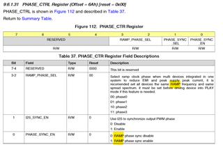
Also on the same page: what do you mean with RAMP clock phase or RAMP frequency? I must have missed the meaning of RAMP. Therefore what does RAMP phase sync do exactly?


I am asking because I would like to sync a lot of TAS5806MD devices together and by chance also sync it with a buck regulator.

  • Hello Severin,

    You can only sync the PWM phase selection of up to 4 devices together. RAMP clock is an internal clock in our clock tree that is used for the PWM generation. The output PWM frequency can be configured 384k,480k,576k, and 768k which would be 8x,10x,12,16x LRCLK respectively.

    best regards,

    Luis.

  • Hello Luis,

    why can I only sync 4 devices? If I use for example 5 TAS5805MD I could halt the I2S for all devices, configure the sync-register of 4 devices on the first i2c bus and 1 device on the second i2c bus, then restart the I2S for all of them. Is this assumption wrong if they all get the same I2S signal?

    Also does the PWM output of the amplifier start with
    1) always with a rising edge
    2) or always with a falling edge
    3) or same edge as LRCLK (if first edge of LRCLK is high -> first edge of output is also high)
    4) or totaly random

    Best regards,
    Severin

  • Hello Severin,

    I should clarify that was in regards to phase selection for the EMI improvement mitigation, but you should be able to sync all devices to the I2S bus

    I2S halt and back is the trigger signal for multiple device PWM sync. So the sequence should be:

    1. Initialize TAS5806MD by following startup sequence requirements.
    2. After initialization,  refer multiple device PWM steps to halt I2S, configure I2C, then back I2S.

    best regards,

    Luis

  • Hello Luis,
     
    thanks for your response! Could you also tell me you opinion on this question:

    After syncing als amps together an setting them in play-mode again, does the PWM output of the amplifier start with
    1) always with a rising edge
    2) or always with a falling edge
    3) or same edge as LRCLK (if first edge of LRCLK is high -> first edge of output is also high)
    4) or totaly random

    I am asking, because I could generate a clock from a microcontroller which is in sync to the output of the TAS5806MD. I could then use this clock to sync it to a buckconverter. I am also intersted in your opinion if this is even usefull.

    best regards,
    Severin

  • Hello Severin,

    I will test this on bench and get back to you.

    best regards,

    Luis

  • Hello Severin,

    The PWM rising edge/falling edge would be inconsistent as it would depend what point the device is brought up with the I2S and how long it takes within our internal clock tree for the PWM to start up. You might consider using LRCLK for your buck converter especially since the clock is always there compared to the PWM can configured to start and stop(when it enters hi-z or sleep/deep sleep).

    best regards,

    Luis

  • Hello Luis,

    thanks for your help. I will use the LRCLK for the buck converter.

    best regards,
    Severin