Other Parts Discussed in Thread: PCM5121,
Scenario: PCB with 2x TAS5755 and 1x PCM5121 supplied with MCLK(512xfs), BCLK, LRCLK and SDATA in I2S 24-bit 48khz.
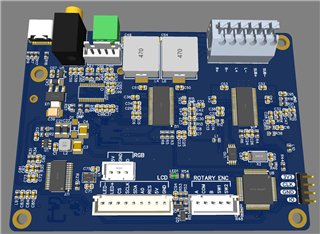
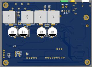
I'm facing an issue with the TAS5755M when PVDD voltage is between around 15V and 24V. I have designed a PCB with two TAS5755M amplifiers. One (Labeled AmpLR) is for stereo speakers in 2.0 BD mode. The other TAS (labeled AmpSUB) is for a subwoofer in PBTL BD configuration. Everything works great when PVDD is supplied from a 12V power supply. When switching over to a 24V power supply, the AmpLR TAS doesn't start up properly, while the AmpSUB one shows no problem.
Taking a look at the I2C registers it appears as if the I2C address isn't latched properly during startup or the TAS is reset. The AmpSub is getting the AmpLR configuration. Delaying the configuration for a few seconds, doesn't resolve the issue, the registers for both chips are then configured correctly, but the AmpLR TAS produces no sound. I really can't figure it out: the design for both chips are nearly identical barring the PBTL configuration of the one.
What I have determined so far:
1. Using a variable power supply, starting up with < 15V and then increasing the voltage after configuration, everything works as expected.
2. Supplying only AVDD and VDD and NO PVDD (PVDD disconnected), configuring the TAS5755M and then only applying PVDD, everything works as expected.
I realize the datasheet makes specific mention of power sequencing, but having studied the EVM's schematic, it did not appear to be that important since the EVM makes no provision for proper sequencing as per the datasheet. The PCB uses the same input for PVDD to step down to 5V and 3V for the microprocessor and TAS5755M's. So it is likely that PVDD will be supplied before AVDD and VDD reach 3.3V.
Can anyone shed some light as to why I'm getting this strange behavior.
Another issue that I noticed too, the TAS5755 will not achieve PLL lock without MCLK being supplied despite the datasheet mentioning it should work without MCLK. The PCM5121 on the PCB locks without MCLK, but does require manual clock configuration. I2S is supplied from a XMOS breakout board.
Herewith the configuration:
bool TAS5755::initialize()
{
    bool result = true;
    result &= writeRegister(0x1b, 0x00);  //Set oscillator trim to factory calibrated
    ThisThread::sleep_for(50ms);
    result &= writeRegister(0x05, 0x48);  //Enter all channel shutdown
    ThisThread::sleep_for(10ms);
    result &= writeRegister(0x10, 0x07);  //Set Max PWM duty cycle for >18v power supply
    result &= writeRegister(0x02, 0x00);  //Clear errors
    result &= writeRegister(0x03, 0x80);  //Soft unmute
    result &= writeRegister(0x0e, 0x92);  //Slow volume slew rate
    result &= writeRegister(0x11, 0xb8);  //Set timings for BD 2.0 mode
    result &= writeRegister(0x12, 0x60);
    result &= writeRegister(0x13, 0xa0);
    result &= writeRegister(0x14, 0x48);
    uint8_t bufTimings[4] = { 0x00, 0x89, 0x77, 0x72 }; //Set multiplexer for BD 2.0 mode
    result &= writeRegister(0x20, bufTimings, 4);
    if (pbtl)
    {
        //p24 9.3.3 PBTL https://www.ti.com/lit/ds/symlink/tas5755m.pdf
        uint8_t bufMux[4] = { 0x01, 0x10, 0x32, 0x45 };
        result &= writeRegister(0x25, bufMux, 4); //PWM MUX
        result &= writeRegister(0x19, 0x35);  //Shutdowns
        //https://e2e.ti.com/support/audio-group/audio/f/audio-forum/710402/tas5755m-asking-for-the-tas5755-pbtl-and-the-drc-setting
        uint8_t bufCh4Src[4] = { 0x00, 0x00, 0x42, 0x03 };
        result &= writeRegister(0x21, bufCh4Src, 4); //CH4 Source Select
        uint8_t bufCh4InputMixer[8] = { 0x00, 0x40, 0x00, 0x00, 0x00, 0x40, 0x00, 0x00 };
        result &= writeRegister(0x61, bufCh4InputMixer, 8); //CH4 Input Mixer
        uint8_t bufCh2OutputMixer[12] = { 0x00, 0x00, 0x00, 0x00, 0x00, 0x00, 0x00, 0x00, 0x00, 0x80, 0x00, 0x00 };
        result &= writeRegister(0x52, bufCh2OutputMixer, 12); //CH2 Output Mixer

        //Biquad 0x5a and 0x5b registers (BQ4a on GUI) can used for DSP
    }
    ThisThread::sleep_for(250ms);
    result &= writeRegister(0x05, 0x08);  //Exit all channel shutdown

    return result;
}

...
TAS5755 amplr(&audioI2C, AMPLR_ADDR); //Start in BTL mode, addr: 0x34
TAS5755 ampsub(&audioI2C, AMPSUB_ADDR, true); //Start in PBTL mode: addr: 0x36

main.cpp
{

  AmpLrPowerDown = 0;
  AmpSubPowerDown = 0;
  ThisThread::sleep_for(10ms);
  AmpLrPowerDown = 1;
  AmpSubPowerDown = 1;
  ThisThread::sleep_for(10ms);
  AmpReset = 1;
  ThisThread::sleep_for(250ms);
  amplr.initialize();
  amplr.setVolume(-6.0f);
  ThisThread::sleep_for(100ms);
  ampsub.initialize();
  ampsub.setVolume(-6.0f);
}
I'm not sure if there might be EMI interference from the output inductors being too close to the TAS chips perhaps? Attached is the schematic.