Hi team,
My customer now use TAS5414BTDKDRQ1 and could you kindly help to check SCH?
When TAS5414B powerIC as a slave, is it necessary to provide a clock signal through OSC_SYN from outside?
This thread has been locked.
If you have a related question, please click the "Ask a related question" button in the top right corner. The newly created question will be automatically linked to this question.
Hi team,
My customer now use TAS5414BTDKDRQ1 and could you kindly help to check SCH?
When TAS5414B powerIC as a slave, is it necessary to provide a clock signal through OSC_SYN from outside?
Hi Amelie,
The schematic looks fine. OSC_SYN can be from outside source, but it must meet device requirement.
Regards,
Derek
Dear TI,
we use two TAS5414B powerIC as slave in our product, if we don't use outside source(OSC_SYN), is it possible?
Meanwhile if we don't use outside source(OSC_SYN), could you pls recommand how to design circuit?
Thank you very much if you can give feedback in time because the project is urgent.
Hi Amelie,
Yes, it is ok. You can refer FOSC_SYNC spec requirement in datasheet, page 10.
If you do not use outside source(OSC_SYN), you should set device to master mode. Or the clock source is from another master device, for master device OSC_SYN is output.
Regards,
Derek
Dear TI,
accoding to the communication, we plan to design one powerIC config as master device, and another powerIC config as slave device. the master device output clock to slave device.
meanwhile the device as master or slave doesn't affect the i2c interface, the outside i2c master device also can't write/read the master poweric device and slave powerIC.
could you pls help to check the design and understiong corrct or not?
Thank you very much if you can give feedback in time because the project is urgent.
On the schematic delete C57122 and R53227, and short I2C_ADDR pin to ground. This will allow the I2C_ADDR pin to be set accurately and IC57001 to be the master. On IC57000 delete C57120 to make this device a slave (I2C address for Slave3). Net AMP1_SYNC and AMP2_SYNC should be connected together. The Master will provide the oscillator for the slave, by setting bit D7 in Register 0x0B. The slave device needs an oscillator to function, it does not need to be enabled in Register 0x0B, bit D6, as it is automatic.
Regards,
Gregg Scott
Dear Scott,Derek,
we use two TAS5414Bs in our product, one is master and another is slave, the master provide the clock to slave. could you please help to provide the register configuration both master and slave to me?
Thanks!
Best Regards
Jeremy
Dear TI,
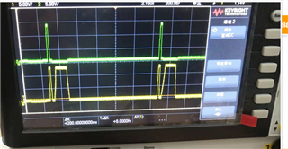
The output P and M waveform is shown below during power on. After then there is no any signals. Could you help to tell me the reason?
The syn clock is 3.3MHz can be detected from master.

the register configuration is shown below:
master:
| register address | register data |
| 0x8 | 0xAA |
| 0x9 | 0xF0 |
| 0xA | 0x4D |
| 0xB | 0xDF |
| 0xC | 0x00 |
| 0xD | 0x00 |
| 0x10 | 0x05 |
slave:
| register address | register data |
| 0x8 | 0xAA |
| 0x9 | 0xF0 |
| 0xA | 0x0D |
| 0xB | 0x5F |
| 0xC | 0x00 |
| 0xD | 0x00 |
| 0x10 | 0x05 |
Jeremy,
Use the FFT function on you AP. This will tell you the frequency of the noise. Noise and THD this is usually a set up issue or a ground loop issue.
Regards,
Gregg Scott