


Hi,
we are now quite some time failing to startup the TAS5733L Amplifier without having it set the error register bit for overcurrent/undercurrent or temperature fault, although everything we can measure seems within recommendations, so we would appreciate very much any help and pointers!
Layout looks like this, we can measure i2s at 3.078Mhz when we do stream after startup sequence, we do measure 3.3V / 12V and do adhere to the minimum wait times depicted in TI datasheet document.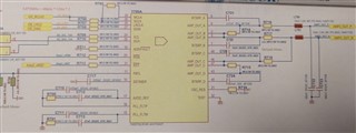
So we are probably complying with the necessary clock rates (mclk "faked" by connecting to SCLK).
We exported Configuration from PP3 application, and are simply applying it trying to adhere to the datasheet by placing trim oscillator and an appropriate wait time at the top instead of the order that comes from the PP3 export (where trim is called in the middle of config settings).
We can see all bits correctly travelling on the i2c bus on an oscilator and reading registers let's us conclude, the TAS5733L has set them as desired.
Nevertheless, we do never hear any sound, nor can we see the 0x02 error register at 0x00 - it is always with the second bit set as 0x02.
If needed we can also send an image of the oscilator showing the timing of pins nRST, nPDN, 3V3 and 12V, but they should be complying absolutely with datasheet requirements (always maintaining minimum times and low/high barriers).
