This thread has been locked.
If you have a related question, please click the "Ask a related question" button in the top right corner. The newly created question will be automatically linked to this question.
hi,
PCM4222 work in PCM mode and sclk=12.288Mhz, normal mode. sample rate is 48khz.
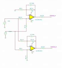
below is my design that produce P/N diff signal to PCM4222 analog input.
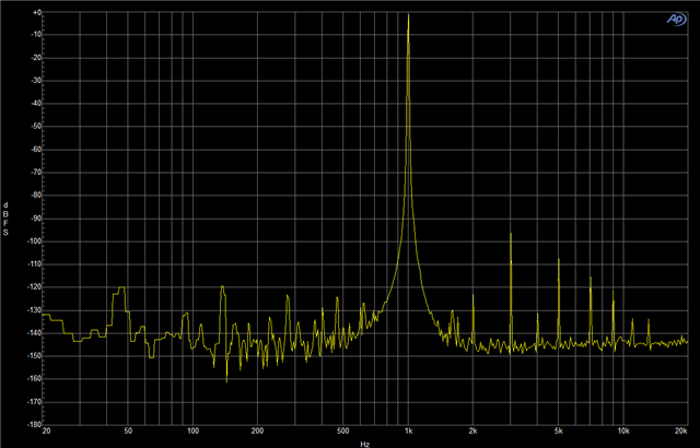
when below PCM4222_P/N port not connected to PCM4222 analog input, THD is very good about -120dbc@1khz 2.6 Vpp sin signal(measure by instrument, not through PCM4222 sample data's fft analysis).
but when PCM4222_P/N port connected to PCM4222 analog input, THD become very bad about -100dbc. and when no sclk 12.288M clock input to PIN35 master clock, THD recover to -120dbc.
i guess PCM4222 's sample hold circuit has affect amplifier's THD performance. can you help to provide some method to avoid sample hold circuit influence? thanks!
BTW, below design is not a symmetry design and maybe have some defects.
sorry,some mistake in above discribition .
when PCM4222_P/N port connected to PCM4222 analog input, THD become very bad about -90dbc. HD2/HD3/HD4 are all very obvious above noise floor.
i guess when 12,288M master clock input PCM4222, it's sample and hold circuit works, and above U12/U2's load changed accordingly.
i change R13/R14 from 0ohm to 20ohm to 100ohm, THD has little improve about 2-3db.
Hi Jung,
I will need a couple days to look into this. sorry for the delay.
Regards,
Arthur
hi arthur,
as datasheet shows pcm4222 has typical THD+N=-108db when input=-1db;PCM mode;48k sample rate;
can you use EVM board to show FFT plot in above test condition? thanks!
hi arthur,
above fft plot i shown use about 16368 sample point and add hanning window.
Hi Jung,
Yes, I will take an EVM and measure the fft as you described above
Regards,
Arthur
Hi Jung,
Is the FFT spectrum that you shared measured at the input pins of the PCM4222? or is this measured at the ASI output of the ADC?
Regards,
Arthur
hi arthur,
PCM4222 works in PCM master mode, output data format is Left-Justified and i use ADC sampled data from PIN32 to convert to FFT plot.
Hi Jung,
I measured THD+N on an EVM for the setting you described, and at a -1 dBFS output I am getting -93.7 dB THD+N.
Here is the FFT plot I gathered
Regards,
Arthur
hi Arthur,
EVM fft plot same as my test results, HD3/5/7 are very high. so i want to know how datasheet achieve -108db thd+n performance?
is there any way to improve EVM performance?
Hi Jung,
I would look at Your SCLK input. jitter on this signal can worsen THD.
Also please try to use low voltage coefficient capacitors for C3, C12 (capacitors whos capacitance does not change much across voltage) such as a film capacitor. this note applies to any capacitors on the input signal/
It may also be helpful to place a 0.1uF capacitor across IN+/IN- to improve signal integrity.
Regards,
Arthur