Other Parts Discussed in Thread: TINA-TI
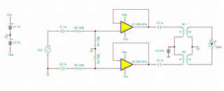
I believe this needs to be approached as kind of a "power management" question, I don't think you have high-voltage power BJTs in your product line but I'm sure there's familiarity with this issue, I am trying to design a subsystem using them to replace a pair of vacuum tubes coupled to their load through a low-frequency wideband transformer with a center-tapped primary connected to +475 volts B+. I'm connecting them as complementary current sources to each end of the power transformer which happens to be driven by either output of an OPA1678, and the inputs to each side are AC-coupled so they "cross over" at virtual zero on the input waveform. (The circuit has some complications to move the "cathode return" above ground so the input waveform can go negative but I don't want to get into THAT at the moment, that part of the circuitry seems to be well under control.) So I was having trouble because the device that was supposed to be "off" was in reality somewhat "breaking down" when the device that was SUPPOSED to be "on" was conducting, because the "free end" exceeded breakdown when the other end pulled current. The issue I was having isn't really about the transistors breaking down, it was the "free" end pulling current the WRONG WAY and screwing around with the baseline of the transformer! I was sort of gobsmacked because the devices I selected were VCEO 450 volts VCES 1,000 volts, and the bases were driven to the emitter level so VCES should apply. When I replaced these devices with others that have VCEO 800 volts VCES 1600 volts, the circuit is working great! It seems like I have a genuine misunderstanding about what VCEO and VCES actually mean, could you enlighten me? I really don't want to get in trouble getting into production even with the NEW devices and seeing this problem return, if the power device would just BURN OUT I would have to replace it and I could live with that, but this sort of "soft fail" could drive the test techs crazy, and leave the customer bewildered too! (I thought about simulating this with LTSpice but my luck simulating transformers in Spice has been less than stellar, there aren't any "default" transformers anything close to what I need.) Thank you for looking into this!


