This thread has been locked.

If you have a related question, please click the "Ask a related question" button in the top right corner. The newly created question will be automatically linked to this question.

TAS5414C-Q1: TAS5414C-Q1

Part Number: TAS5414C-Q1

Dear. Experts.

I am using the TAS5414CQ1(silked on chip as XTAS5414CQ1) as the master.
I have some problems.

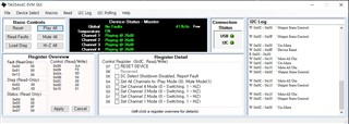
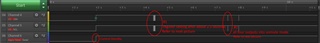
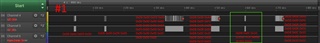
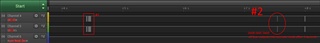
1. In the Play All or Mute All state, pop noise occurs when controlling individual channels as shown below.(and vice versa)
This is also happening on your EVM board.
W 0x0C 0x00 -> 0x0C 0x03
W 0x0C 0x00 -> 0x0C 0x0C
W 0x0C 0x00 -> 0x0C 0x0F
W 0x0C 0x10 -> 0x0C 0x03
W 0x0C 0x10 -> 0x0C 0x0C
W 0x0C 0x10 -> 0x0C 0x0F

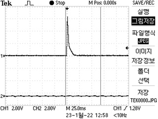
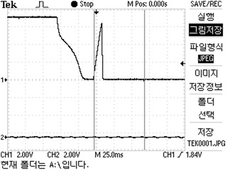
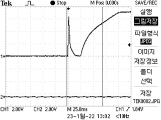
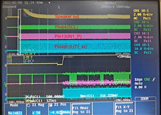
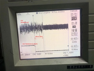
At this time, the waveform of the mute pin is as the attached file. Is this waveform normal?

I have attached my setting values and circuit diagram. Please advise on how to avoid pop noise.

2.Separation is not good in our product.
For example, when 1 KHZ signal is connected to R CH and no signal to L-CH, the signal of RCH is output to L-CH with low sound.
When checking the L-CH input with the scope, there is no signal interference, but you can hear a small sound with the SPEAKER.
DIGITAL AMP seems to be interfering. Could you please review what could be the cause?

Thank you.

CMM30_AMP_PCB_2022-0123-1109-1.pdf

  • James,

    About question 1: From the waveform looks like device start output again after mute. May you capture the PWM waveform along with this final output waveform? with that we can understand better how the sequence.

    About question 2: Did you measure with AP how much is the separation level? typically sepeartion problem comes from two part:

    1. analog input is coupled to another channel. 2. output inductor is an open frame inductor with strong leakage and coupled to another channel.  

    Will you please do some isolation on the two factors?

    Dylan

  • Dear. Yao

    Thank you for your quick response.

    I have re-arranged my question as follows. Please check again.
    1. Control the STANDBY pin from LOW to HIGH and send W: 0x0C 0x10 or W: 0x0C 0x00 after about 500mS to generate small noise. Noise seems to occur as it changes from Hi-Z state to None Hi-Z state. Is there any way to solve this noise?
    Is there a power-up sequence? Can you give me any documentation related to this?

    2. During normal operation (all channel play), if W: 0x0C 0x03 or W: 0x0C 0x0C is sent, pop-noise occurs. This problem also occurs in your EVM. Is there any way to solve it?

  • James,

    Thank you re-arrange your quesiton. Basically i understand your quesiton, while something abnormal seems happens in the waveform and makes this noise. Some suspection points are: i see mismatching happens at input P and input M, as P and M should see same impedance to make sure bias voltage is set up at same rise edge. while R343 and R3 are used at P, nothing at M.  

    Will you try to remove the R343 and R3 to see if noise reduced?  the same to other channels.

    Addtionaly, i still want to make sure if there other reason. So please capture the PWM waveform along with this final output waveform? with that we can understand better how the sequence.

    1. Control the STANDBY pin from LOW to HIGH and send W: 0x0C 0x10 or W: 0x0C 0x00 after about 500mS to generate small noise. Noise seems to occur as it changes from Hi-Z state to None Hi-Z state. Is there any way to solve this noise?
    Is there a power-up sequence? Can you give me any documentation related to this?

    Dylan

  • Hi James,

    Dylan is out of the office for Chinese New Years.  Let me explain how the the Standby and Mute work on this device.

    1. When the TAS5414C-Q1 transitions from HI-Z to Mute the outputs go from Non-Switching to Switching.  The transition time is called Tcm for common-mode ramp.  During this time the PWM ramps to 50% duty cycle and is designed to be as pop-free as possible  It will do this with both of your register commands.

    2.  Once you are passed the Common-mode ramp phase the channels cannot be placed into and out of Hi-z by themselves without a pop.  This is due to the lack of the Tcm time.  The Tcm time and Tgain (Gain ramp time) are only used when all 4 channels are in transition.  There is not cure for the pops you hear, except to place all four channels into Mute and into Hi-Z at the same time.

    Regards,
    Gregg Scott

  • Dear. Dylan

    Sorry, but we don't have the equipment to see the full data.

    When the power is on, the first data sent is as follows.

    (The lower four waveforms are zooming of the square part.)
    1. R: 0x00 (Check for protection field and compare 0x00)
    2. W: 0x0C 0x10
    3. R: 0x00 ~ 0x13 (Read all data)
    4. W: 0x08 ~ 0x10 (Write all data)

  • HI James,

    I have commented your code as follows:

    1. R: 0x00   #read the fault register to clear any faults
    2. W: 0x0C 0x10  #place all four outputs into mute mode.  Outputs are switching at 50%, no audio present
    3. R: 0x00 ~ 0x13   #read all the registers 
    4. W: 0x08 ~ 0x10  #write all the data

    This should be changed a bit. I would move step 2 to the end.  Do not enable the outputs until the register settings have been performed.   At what step do you get a pop?  When do you unmute the channels?

    Regards,
    Gregg Scott

  • Dear. Scott

    Thank you for your great supporting.

    I can hear the pop noise in step 2.
    When the media IC is decoded, the mute is released (about 2-3 seconds after step2 is executed)

    As you said, I modified it as below, but still pop noise occurred in step 5.
    1. R: 0x00 #read the fault register to clear any faults
    2. R: 0x00 ~ 0x13 #read all the registers
    3. W: 0x08 ~ 0x10 #write all the data with read all the registers value(0x0C register value is 0x1F)
    4. delay 10ms
    5. W: 0x0C 0x10 #place all four outputs into mute mode. Outputs are switching at 50%, no audio present
    6. W: 0x0C 0x00 #place all four outputs into unmute mode after 2-3 seconds.

    My opinion is that pop noise is closely related to STANDBY .
    Pop noise occurs when the above process is executed after controlling STANDBY from LOW to HIGH.
    However, there was no Pop noise in the STANDBY keep HIGH state.
    I've talked about it before. Noise seems to occur when changing from Hi-Z state to none Hi-Z state.
    What do you think?

  • James,

    When are you operating the /STANDBY pin?  Standby mode should be released before step 1.  Standby mode will reset the I2C.  It should only be used when the system is first turned on and when the system is finally turned off.  

    Regards,
    Gregg Scott

  • Dear. Scott

    I set the Standby pin high about 2.5 seconds ago.
    I captured the waveform of the I2C communication line and the STANDBY pin.
    Hope the attached images are helpful.

  • Hi James

       We'll spent some time discuss it.

  • Hi James,

    Can you describe how you are testing the pop noise?  There will be some very low level pop in most amplifiers.  Usually is not noticeable.  

  • The pop noise when setting the value was accepted by our customer.
    Thanks for your help.
    Our H/W design team has a question.
    If I apply H/W MUTE without S/W MUTE, the sound completely stops after about 18mS.
    The waveform for it is shown in the attached figure.


    Is this normal behavior?

  • Hi James,

    This depends on the method of H/W mute.  There may be a 18ms discharge time of the Mute Cap.  Therefore, I would think this is normal.

    Regards,
    Gregg Scott