This thread has been locked.

If you have a related question, please click the "Ask a related question" button in the top right corner. The newly created question will be automatically linked to this question.

TPA6166A2: Audio forum

Part Number: TPA6166A2

We faced one compatibility issue for TPA6166 headphone AMP.

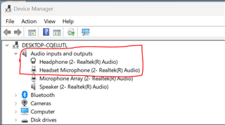
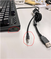
  1. A keyboard with audio cable caused windows device manager failed. The Headphone didn’t disappear when we unplug the phone jack from keyboard 3.5 jack, and the headphone auto detect function was failed.
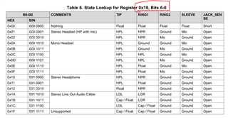
  2. After check with TPA6166 datasheet we found the return information was not in list of table 6 register 0x19, bit 6-0.
  3. The I2c feedback to EC was list below

 1. Fail symptom, Keyboard’s phone jack inserts into TPA6166 jack, ( no headphone on keyboard )

The MCU read register 0x19 and compare the result to table 6 in datasheet, there is an abnormal value appear (0x21) as below

B6-B0 is not on list of table 6 ( incorrect )

HEX         BIN

0x21        0010 0001

 2. Normal Symptom, Keyboard’s phone jack on TPA6166, then insert headphone into kayboard’s jack.

B6-B0 is 02, ( correct )

HEX         BIN

0x02        0000 0010


 Any idea of this fail value?

What is correct register reading process for headphone jack detecting?
Is there any other register value need to be read before 0x19?

Because the IRQZ kept at LOW/HIGH when fail happened,
Is it possible to reset IRQZ by I2C register?

We can't find detail headphone detect algorithm in datasheet,
Could you have a brief description how this hardware detecting algorithm of TPA6166?

  • Hi Henry,

    I got a bit confused on how the problem happens:

    • Is TPA6166A2 integrated into this keyboard with 3.5mm jack?
    • Or is this keyboard interacting in some way with the TPA6166A2EVM while both are connected at the same time?

    IRQz can be reset by reading the responsible register that caused the interrupt to trigger.

    Jack detect feature works in a similar way to the described in this document: https://www.ti.com/lit/an/slaa454/slaa454.pdf

    Best regards,
    -Ivan Salazar
    Applications Engineer

  • As I said previously, there is no large number rate particular. Slew rate influences PLL commotion, our suggestion is utilize a higher slew rate reference clock if conceivable.
    With SE input, albeit the datasheet determined a min. of 1.4V OSCin, we really can uphold down to 0.8V. https://magnum4d.me/ 
     I don't why the client definitely dislikes 2.4V, we really want to troubleshoot.
    What number of board has this issue? In the event that design the info support to differential sort, will it lock? Might you at some point give Spasms Master design document to us to survey?

  • HI Lars,

    I think you may have posted in the wrong thread, please let me know otherwise.

    Best regards,
    -Ivan Salazar
    Applications Engineer