This thread has been locked.

If you have a related question, please click the "Ask a related question" button in the top right corner. The newly created question will be automatically linked to this question.

PCM5102A: PCM5102A can't export output

Part Number: PCM5102A
Other Parts Discussed in Thread: PCM5102, LM4871

Hi team,

Customer has some questions.

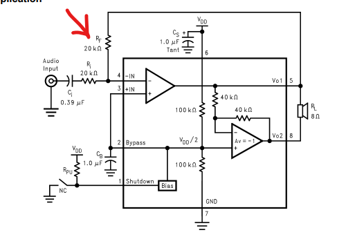
im trying to connect like below image. (PCM5102A - LM4871M - Speaker)

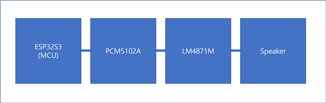
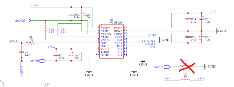
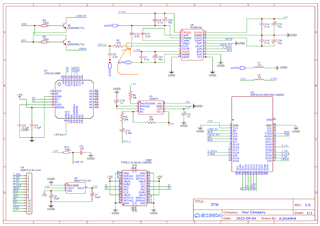
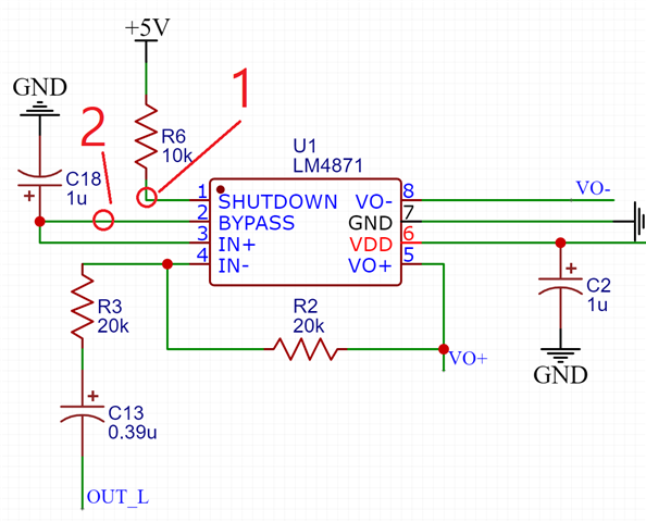
so i designed the circuit like below schematic. 

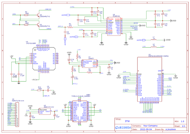
it's connected by i2s between esp32s3 and PCM5102A.

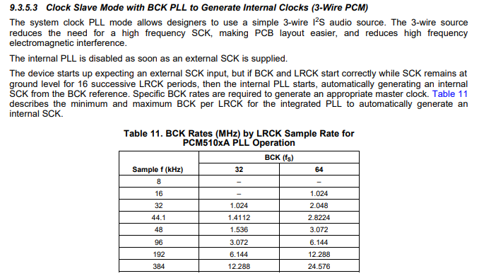
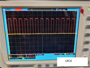
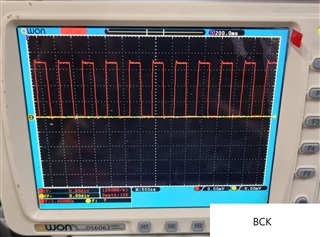
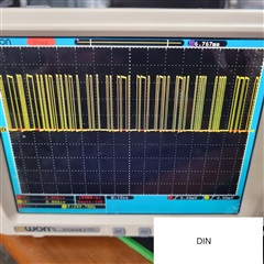
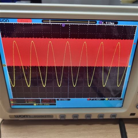
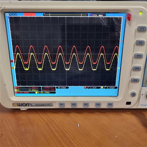
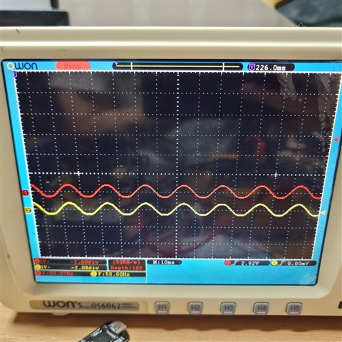
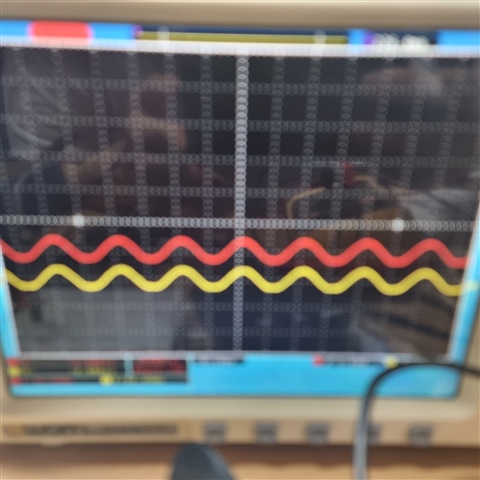
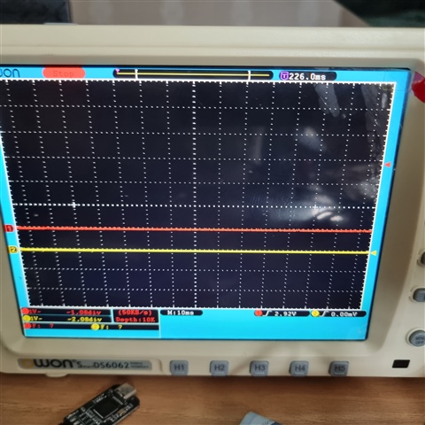
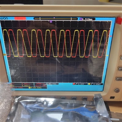
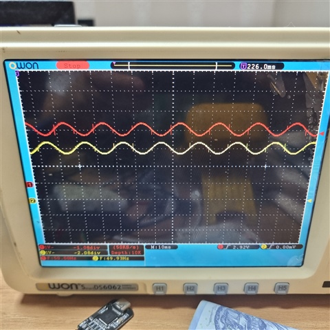
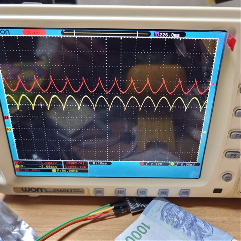
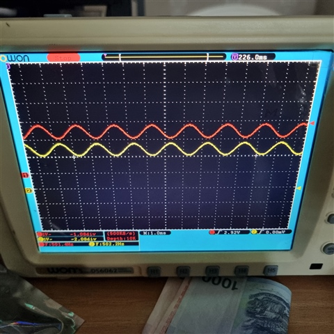
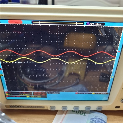
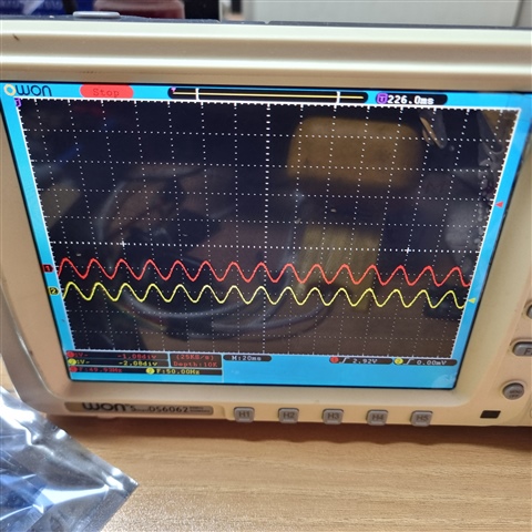
when i probing the pins by using the oscilloscope, esp32s3 send out signal from BCK, LRCK, DATA. and MUTE was set to LOW.

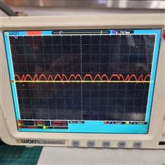
but PCM5102A can't export output(OUTL).

to solving problem, First i wish to check circuit.

is there any problem in my schematic?

if there is a problem, could you let me know why?

Could you help?

Thanks & Regards,

Vivian

  • Hi Vivian,

    I don't understand "but PCM5102A can't export output(OUTL)"  Can you elaborate?  Are you saying that pin XSMT on the PCM5102A is low and there is no output on PCM5102A?  Yes, the host processor needs to set this to high.

  • Hi Jeff,

    Thanks for your quick reply.

    Customer replied

    -------------- -------------- --------------
    sorry, my mistake.

    despite my code set XSTM(MUTE) is HIGH, pcm5102a is no send OUTL signal.

    'but PCM5102A can't export output(OUTL)' means the 'OUTL' pin is measured to be approximately 0V.

    Very low and irregular waves are measured, but they cannot be seen as normal signals.

    Measurements were made using an oscilloscope on GND and OUTL.
    -------------- -------------- --------------

    Could you help again?

    Thanks & Regards,

    Vivian

  • HI Jiahui,

    Is this the first time trying to get output from OUTL with this system?  Or does this happen under certain conditions?  

    -Jeff

  • Hi Jeff,

    Customer replied

    it's first time.
    After designing schematic, i have never been heard the sound of LM4871 or seen the signal of PCM5102.
    i think that i properly desgin schematic of both PCM5102A and LM4871.
    and even if i replace new PCM5102A, but issue still occur. (also LM4871)
    so i don't know what i should check for output signal.

    Could you please help?

    Thanks & Regards,

    Vivian

  • Hi Vivian, 

    Have you checked the digital input for timing and the setup is correct?  The device will just output 0V if the digital input is not set up correctly.

    What is your BCK and Fs?  Could you possibly share a scope shot of the BCK DIN LRCK?

    -Jeff

  • Hi Jeff,

    Thanks for your reply.

    Here is the content

    my sample_f is 441000 and i think bck is 1.4112 because it use only left channel.
    when i probe each pin, it seems to be normal.

    i attach each shot.
    data(DIN) is digital signal of sine wave.

    Could you help?

    Thanks & Regards,

    Vivian

  • Hi Vivian, 

    I don't see any issue with your timing.  So this has never been seen to work yet?  Can you check the all 3 supply voltages?

    Also, I see that you have a 1mH inductor connecting AGND to GND?  This may be an issue.  If you can just try to replace this with a 0 ohm jumper.

  • Also, please check VNEG on the scope.  This should be -3.3V DC.  

  • Hi Jeff,

    Thanks for your reply.

    Customer replied:

    -----------------------------------------------------
    oh sorry. I forgot to explain 1mH.

    I didn't have ferrite beads in the design program,
    so I used an arbitrary 0603 pad size on the PCB, marking it as 1mH.
    In reality, there are ferrite beads attached. (ferrite beads model : KMZ1608DHR241CTD25, 240Mhz, 0.6ohm)

    Even though a signal was sent, it never worked.

    three voltage of the PCM5102A is measured about 3.3v
    also VENG is measured about -3.3V.
    -----------------------------------------------------
    Could you help?
    Thanks & Regards,
    Vivian
  • Hi Vivian,

    Can you confirm that this a shorted jumper ?  We should try a 0 ohm jumper to see if any improvement.

    -Jeff

  • Hi Jeff,

    Thank you for reply.

    Here is the new reply from customer
    ------------------------------------------
    when i check both AGND-GND and 3.3V-3.3VA, these are shorted.

    i will try to test with a 0ohm, i just ordered that.

    can ferrite beads cause some problems?
    ------------------------------------------

    Thanks again.

    Best regards,

    Vivian

  • HI Vivian,

    Yes, the ferrite bead could be the issue.  For just experiment, you could unsolder the FB and solder in just a piece of wire to short it.  Then we can know quicker.

    -Jeff

  • Hi Jeff,

    Even though I use a 0 ohm resistor, it still doesn't work.

    If I probe that (in the image), it shows me less than 1V.
    I think it's not outputting because it's too low and it's not sine wave.
    In reality, there is no sound coming from the speaker.
    It was the same before it was changed to 0 ohm.
    is this normal?

    if it's not normal, Are there any checkpoints for this issue?

    Thanks & Regards,

    Vivian

  • Hi Vivian

    Hmm.. Do you have another board to try?  Maybe the device got damaged.  I will keep thinking..

    Can you measure the quiescent current from 3.3V supply?  Can you see it change when you enabled the device?

    -Jeff

  • Hi Jeff,

    I will purchase a new PCM5102.
    Once I replace it, I will respond with the result.
    Is there a way to identify faults in the PCM5102?

    Thanks & Regards,

    Vivian

  • Hi Vivian,

    Does the waveform change when you change the digital input?  What was your input with the scope plot you provided above?

    If you had an EOS issue, the device could have been damaged.   Many times EOS will short the DUT pin to GND or supply.  You could do a diode continuity test on the pins vs GND to see if there are any shorts.

    -Jeff

  • Hi Jeff,

    Good day.

    I haven't changed my digital input yet.
    i will check this next week.

    When a sine digital signal is input, the scope shows a wave like the one in the above image.
    can you need sample code?
    Looking forward to your response

    Thanks again.

    Best regards,

    Vivian

  • Hi Vivian,

    I do not know your critita for constructing the sine wave, i.e. Fs, num samples, etc.  I believe you can use a free program called Audacity to construct it and make sure it's correct before sending it to the DAC.

    -Jeff

  • Hi Jeff,

    thank you for reply

    ----------------------------------------

    Does that mean, make a file and the MCU reads it and sends it to DAC?

    Until now, it has sent signals by changing the value to i2C communication sample code without a file.
    ----------------------------------------

    Thanks again.

    Best regards,

    Vivian

  • Hi Vivian,

    I'm not exactly what tools you are working with, but yes, it would need to be constructed what is sent over the I2S line.

    -Jeff

  • Hi Jeff,

    oh sorry, i used i2s, it was a typo
    This week, a new PCM5102 will be delivered to me. I will replace it as soon as I receive it.
    i will check this problem and reply result.

    Best regards,

    Vivian

  • Hi Vivian,

    Ok, please let me know the results when you get them.

    -Jeff

  • Hi Jeff,

    Good day.

    i tested new PCM5102A, but it did not work.

    so i'm checking example code.
    sorry to reply late.
    i think HW is not problem.
    but there may be things i don't know.
    Could you help?
    Thanks & Regards,
    Vivian
  • HI Vivian,

    Please tell me more about the issue.  Did you replace just the IC?  Or is this a fully newly populated board?

    -Jeff

  • Hi Jeff,

    okay, i will let you know if i have any issue.
    i just replace IC(PCM5102A) by using heating gun.
    Thanks & Regards,
    Vivian
  • Hi Jeff,

    the result is that finally PCM5102A export output signal.

    (red line is clock, yellow line is output)
    so this signal send to LM4871 then LM4871 export output signal to speaker.
    but the speaker does not make any sound. (8Ω, 0.25W speaker, supply voltage = 3.3V)
    as a result of referring LM4871 datasheet, It seems to be a normal speaker that can work.
    im trying to solve this problem.
    Thanks & Regards,
    Vivian
  • Vivian,

    I am glad you are making progress.  Can you explain the 2nd scope plot?  Is this the output of the LM4871?  What is the volt/div of the scope?

    -Jeff

  • Hi Jeff,

    yes it's output of LM4871 (VO+, VO-, 2nd image)
    i think reason that high and low is flat is beyond range.(supply voltage 3.3V)
    volt/div is 1V like below image.
  • Hi Vivian,

    Yes, you would be clipping.  Sounds like you got this figured out!  

    -Jeff

  • Hi Jeff,

    yes, but i have a another problem.

    suddenly, my LM4871 is generating the same phase(LM4871 Vo1, Vo2).
    i replace some part and upload new code(same code). but i didn't find reason.
    I'm ensnared in the same intricate situation again. haha;;
    Thanks & Regards,
    Vivian
  • Hi Vivian,

    Can you tell me your gain setting on your amp?  This is set by the Rf 

    BR

    Jeff

  • Hi Jeff,

    i used 20kΩ to Rf, Ri.
    then i used 0.33uF to Ci.
    Rf was not changed while testing.
    i have got 2 versions of PCB.
    one is Vdd is 3.3V and other is Vdd is 5V.(Vdd of LM4871)
    but both show me the same phase. 
    Thanks & Regards,
    Vivian
  • Is Ri = 20k as well?  That would mean unity gain.  Are you getting unity gain or not?  What load are you driving.

    Can you lower the level of the digital input sine wave to see if that helps with the clipping?

    -Jeff

  • Hi Jeff,

    yes Ri is 20k.

    does it matter if it's unity gain?
     
    i use two speaker(8Ω 0.5W, 8Ω 0.25W)

    when i lower the level of input, clipping is lower but it still remain.(maybe a little bit)

    Thanks & Regards,
    Vivian
  • Hi Vivian,

    When you have the speaker disconnected, does it give the same clipping waveform?  

    Can you give me the OUT+ and OUT- scope shot (single ended) with no input signal?  We need to figure out why the phase got inverted?  What changed?

    -Jeff

  • Hi Jeff,

    Thanks for your reply.

    yes. i think output waveform is the same whether the speaker is disconnected or connected 

    ↑ this image is the speaker was connected.

    ↑ this image is the speaker was disconnected.
    sorry to be out of focus.
    ↑ this image is with no signal.(input)
    if i send no signal, output is no wave.
    im confused that output is the same phase.
    i guess the reason is SW, but i can't see clue.
    Thanks & Regards,
    Vivian
  • Hi Vivian,

    With the previous amp, you had a differential output as shown below.  What changed?  

    You are correct, both pins should not be in phase.  Can you return to the previous part and turn the gain down?

  • Hi Jeff,

    Thanks for your reply.

    recently, i replaced the ESP32S3 with a new one because it couldn't upload code.
    but, i don't think new ESP32S3 occur this problem.

    i found the condition in which the speaker produces sound.
    when i check 2 point by using multimeter with short test, speaker make sound. (below image, LM4871 shutdown - bypass or shutdown - in+ )
    so im tring to find that reason.
    when speaker makes sound, scope show this graph.
    I feel like I'm finding something.
    Thanks & Regards,
    Vivian
  • Hi Vivian,

    I'm taking over this discussion while Jeff is out. If I understand correctly, it seems you see output signal in phase from LM4871, but only when you put the multimeter across pins 1 and 2 you can see output signals on opposite phase. Can you confirm that?

    Can you try removing R6 and replacing this with a resistor to GND instead of VDD? Not sure if it's an error in the schematic, but shutdown (pin 1) on LM4871 is active high, which means that if this pin is pull-up the device goes into shutdown mode. I think your observations are as expected based on the below:

    • Normally, pin 1 is pull-up by R6, taking LM4871 into shutdown mode. In this case you see a small amount of the input signal going to the output of the amplifier through the feedback path, thus the "output" signals are in phase.
    • When you connect the multimeter to pin 1, the voltage on this pin is low enough to take the device out of shutdown mode. Then the amplifier is able to operate and output the signals on opposite phase.

    Best regards,
    -Ivan Salazar
    Applications Engineer

  • Hi Ivan,

    Thanks for your reply.

    i find something and i'm in chaos.
    in first, i connected the shutdown pin to GND.
    then, speaker begin to make sound with normal phase.
    but, when LM4871 export normal phase, speaker can't make sound.
    in state of this image, even though phase is different, speaker can't make any sound.
    in state of this image, speaker make sound and sound is not normal.
    this is occur in delay state like delay(1000); 
    if i input no delay code, speaker don't make any sound.
    in second, when i increased up input signal, LM4871 export irregular phase like this video & image
    i can't find any clue of this problem.;
    then i get back to origin input signal, LM4871 export normal phase.
    im searching any information of second image.
    Thanks & Regards,
    Vivian
  • Hi Vivian,

    I'm adding further comments below:

    • Could you please confirm the frequency of the test tone you're playing?
      • For some of the scope captures, the frequency seems to be 50Hz, for others is closer to 90Hz.
      • Is your application intended to play low frequency signals?
    • Have you tried playing a higher frequency tone, eg. 1kHz?
      • Is the result any different in that case?
      • If the behavior changes, I would suggest capturing a few different frequencies to check how the phase and amplitude is affected.
    • For the second capture in your last post, can you please check the signal before and after R1 directly at the output of PCM5102? Is it any different before and after the filter?

    Best regards,
    -Ivan Salazar
    Applications Engineer

  • Hi Ivan,

    Thanks for your reply.

    in my code, i set 100Hz tone for sample f is 44100Hz. but, i don't know why it's measured at 50hz

    I'm not trying to output low frequencies, I just wanted to test.

    i set to multiply previous frequencies by ten times. then speaker make sound.

    I think the sound was too low for the previous frequency.


    this image is 10 x previous frequency.

    this image is 5 x previous frequency.

    but, noise still remain for delay time. it's not wanted.
    this image is the signal before and after R1.
    it seem to the same.
    Thanks & Regards,
    Vivian
  • Hi Vivian

    Can you elaborate on your issue with delay time? Are you using a micro controller and are noticing different results if you add a delay line in the code? How does the delay impact the input signal?

    Best regards,
    Jeff McPherson

  • Hi Jeff

    Thanks for your reply.

    What I mean by "delay time" is function in which is call "delay(ms)"

    this function delay the execution of the code.

    but, the delay function of ESP32S3-arduino framework is consisted of "vTaskDelay(ms / portTICK_PERIOD_MS)".

    so i think that because of FreeRTOS function, i2s signal continuely send DAC(PCM5102A)

    when i replace "delay" function to "for(i=0;i<1000;i++){ }", speaker didn't make noise.

    i'll have to test it a little more, but it's beginning to sound.

    Thanks & Regards,
    Vivian
  • Hi VIvian,

    Thanks for the additional information. It seems this is just on the controller code side now to get the proper signals for the DAC.
    Let us know if there are any further questions related to PCM5102A.

    Best regards,
    -Ivan Salazar
    Applications Engineer