This thread has been locked.

If you have a related question, please click the "Ask a related question" button in the top right corner. The newly created question will be automatically linked to this question.

INA1650EVM: 3 INA1650s fed from one signal

Part Number: INA1650EVM
Other Parts Discussed in Thread: INA1650, DRV134, INA134


Hello,

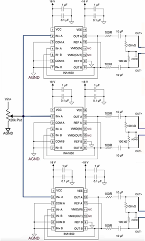
I have a few questions about using the INA1650 as a differential line driver (per Fig 62 of the datasheet):

1) I would like 3 independent outputs, so the input signal (which would come from the output of a 20k pot) will drive (3) INA1650 IC's. 
a.  What would be the input impedance seen by the pot?  250k/3 = 83.3k ?
b.  Do you believe this is high enough for the 20k pot to drive?

2) Do you recommend adding a resistor in series with Pin 2 for each of the INA1650s?  If yes, what value?

3) The outputs will connect to 3-pin XLR jacks. If one were to use an XLR-to-RCA adapter  (which shorts Pins 1&3) to convert from differential to single-ended output, will the INA1650 be ok with this? The DRV134 data sheet shows how the differential output can be converted to single-ended by shorting the OUT- to AGND, but I wasn't sure if this is the case with the INA1650)?

Thank you

  • Hello Vinnie, 

    The input impedance of 83.3k ohm is still fairly high input impedance. For most applications I don't see this being an issue. This will depend very much on the sensor that is driving the input stage. What is feeding the 20 kohm potentiometer? Does the sensor that is driving the front end have a very high source impedance? The main thing is to make sure you aren't loading the sensor too much. 

    The absolute maximum voltage and current on the input pins is shown below. Stresses beyond these can cause permanent damage to the device. As long as these conditions are not violated the device will be ok. Fault protection such as TVS diodes on the inputs to supplies can help clamp input voltages during these events as well. It couldn't hurt to have a set of do not populate pads for TVS diodes on the board just incase you find you need to add them. 

    I'll take a look at the application regarding the DRV and get back to you. 

    Best Regards, 

    Chris Featherstone

  • Hi Chris,

    An INA134 would likely be driving the 20k pot, and the output of the 20k pot would feed the IN+ pins of the (3) INA1650's.  

    Please let me know about my questions 2 and 3 above after you look into it.

    Thanks again!

  • Hello Vinnie, 

    The DRV134 is a different architecture with a 50 ohm series output resistor that when tied to ground keeps the amplifier from shorting. The INA1650 outputs do not have this resistor, therefore the output shorts to ground if configured like the DRV application and isn't recommended. 

    The INA134 is specified with a 2k load. The potentiometer is the main load the INA134 will see. Even if it is in parallel with the 83.3k ohm input resistance the total resistance seen by the INA134 is about 16.1k which is well above the specified 2k load resistance. I don't see this being an issue. With heavier loads lower than 2k ohms the INA134 will have to drive more current. It is specified as shown in the Output voltage vs Output Current plot. The more current the INA has to deliver to it's load, the more the output voltage will droop eventually hitting the short circuit current limit. 

    Best Regards, 

    Chris Featherstone

  • Hi Chris,

    I plan to use 100 ohm output resistors for the INA1650.  So if XLR Pin 1 and 3 are tied together to GND, the OUT- of the INA1650 would need to drive a 100-ohm resistor (and the short circuit current limit will likely kick in if the output voltage gets too high).  Hopefully that will be ok.

    Thanks again!