This thread has been locked.

If you have a related question, please click the "Ask a related question" button in the top right corner. The newly created question will be automatically linked to this question.

OPA1688: Drift in DC output of a precision full-wave rectifier

Part Number: OPA1688
Other Parts Discussed in Thread: OPA210, OPA192

Hi everyone,

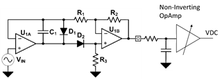
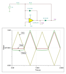
I'm utilizing a precision full-wave rectifier (www.ti.com/.../tidu030.pdf using OPA1688 and CUS10S40H3F) with post amplification ( non-inverting opamp using OPA210) to measure the amplitude of an AC signal with 300 mVpp to 10 Vpp.
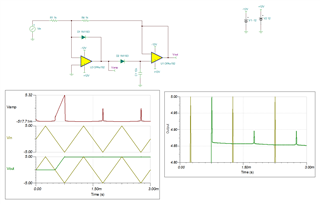
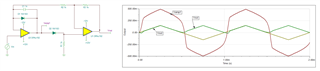
While testing, I observed a drifting output. After investigation I found out that the drift was due to thermal drift in the diodes. Unfortunately the drift is additionly amplified and can't be neglected anymore.

I assume that a peak detector would have the same issue with the thermal drift.

I would appreciate any feedback or suggestions on how to solve this problem.

Best
Hosam

  • Hosam,

    The topology for half wave rectifier that you are using is impacted by the diode drop.  The topology below closes the feedback loop around the diode so that the output tracks the input when rectifying.  Note that this topology is inverting.  This circuit is documented in https://www.ti.com/tool/CIRCUIT060009

    Below is a somewhat different implementation for the peak detect.  The dependence on diode drop is reduced.  

    peak detect 2.TSC

    Let me know if this helps.

    Best regards,

    Art

  • Hi Art,
    thank you for your reply and your suggestion.
    As I understand the proposed topology from TI "Precision Full-Wave Rectifier, Dual-Supply - ">www.ti.com/.../tidu030.pdf performs closed loop control for both negative and positive input signals. Also here, the output will track the input compensating the diode forward voltage; Vout=Vin for positive input and Vout=-Vin for negative input and R1=R2.
    I believe that the half-wave rectifier you are suggesting will have the same thermal drift issue.
    Do you think that the drift in the DC output of my circuit has another source than a thermal one?
    Best regards,
    Hosam
  • Hosam,

    1. I double checked your original circuit again.  I think in my initial analysis I had a wiring issue and I saw that the output included a diode drop.  A diode drop will definitely have a temperature coefficient.  In my analysis today I fixed the issue and I no longer see the diode drop.  Thus, the peak detect should be minimally impacted by the diode drift.
    2. There will be drift due to amplifier input offset drift, bias current and other factors.  The OPA1688 is optimized for audio use (i.e. low noise and distortion).  A device like OPA192 is optimized for low drift (i.e. DC accuracy).  It may be a better choice.  
    3. What level of drift are you seeing?
    4. Below is the revised simulation I did of your circuit.  There is some distorting near the transition from off to on for the diodes.  During this time the op amp will need to slew so that it can overcome the forward drop of the diode.  This could potentially be a source of error.  The OPA192 has a slew rate of 20V/us.  The OPA1688 has a slew rate of 8V/us.
    5. I think to help you resolve this I need detail on the amount of drift you are seeing.  Can you provide data over temperature? 

    Thanks

    Art Kay

  • Hi Art, I'll try the different options and let you know the results.

  • Thanks!  I'm curious to see your results.

    Art