Hi TI team,
We have couple of questions would like to check with you about the PCM6240-Q1.
1. If we want use the I2S, we need to configure the GPIO0/1/2 to SDOUT2.
But since all of the 4 ch are receiving the MIC input then how the SDOUT1 & SDOUT2 gonna process it.
Ex: Once the CH1 ADC completed, we can put that result to SDOUT2 or IC itself will directly move to SDOUT1? Can we change the I2S output channel?
Ex: Once the CH1 ADC completed, the SDOUT1 will directly output that result through I2S line or it will wait till all of the 4ch ADC to complete the process then send out the I2S info?
Ex: Once the CH1 - CH4 ADC completed, will both of the SDOUT1 & SDOUT2 send out the I2S data at the same time?
2. If we have 4-ch ADC , could we adjust the output sequence of CH1 - CH4 based on I2S format?
I notice the datasheet 8.3.1.2 Audio Serial Interfaces chapter mentioned about the setting, it seems that we can adjust the I2S signal in certain slot we want, is that correct?
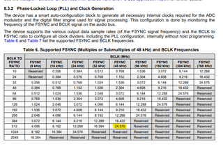
3. If we use TDM format as output, what is the maximum channel we can support based on FSYNC value?
Ex: if we set BCLK as 24.576MHz and the FSYNC is 48kHz, then we can the maximum channel QTY as 24.576MHz / 48kHz / (Word length, 16 bit maybe).
Then we can get 24.576MHz/48kHz/16 bit = 32 CH, is that correct?