This thread has been locked.

If you have a related question, please click the "Ask a related question" button in the top right corner. The newly created question will be automatically linked to this question.

OPA1633: Design review: I/V and MFB filter using FDA for DAC output

Part Number: OPA1633
Other Parts Discussed in Thread: OPA1612, OPA1637,

Hello Mr or Mrs.

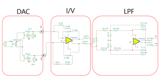
I designed I/V converter and MFB filter with Fully Differential Amplifier(FDA) for output of DAC(AK4499exeq)

I would like to verify the design and have some questions

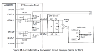
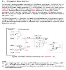
1. In the data sheet of AK4499EXEQ(it is not freely download website), They are using two OPA1612 for I/V conversion each channel.

I think FDA amplifier would be better for performance... thus I plan to replace OPA163x(OPA1633 or OPA1637)

Is it possible to replace OPA1612 to FDA(OPA163x) and is it worthy?

The output of each OPAMP goes to IOUTLN and IOUTLP through Rfb, not opamp input(OPINLN) side.

In the datasheet, IOUTxx pin connected to OPINxx 30ohm.

2. I used OPA1637 for I/V conversion, and OPA1633 is used for MFB LPF because OPA1637 has very low "input current noise" and OPA1633 has very low "input voltage nose".

Do you think it is valid(resonable) assumption? ^^; I am not expert with circuit design.

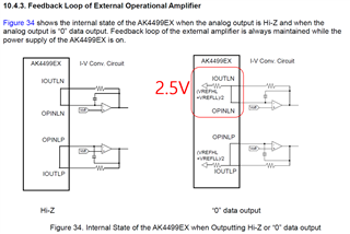
3. I set the IS1 and IS2 set to zero in the TINA simulation because the 'Center Current' is written 0 mA in the AK4499EX datasheet.

Is it correct? The reason why I ask you this is when I increase IS1 and IS2, I/V simulation with OPA1637 is not processed in TINA but OPA1633 works. (IS1 and IS2 = 22.72mA)

 22.72mA is came from 2.5V and internal impedance is 110ohm so... 2.5/110 = 0.02272 (I think it is stupid calculation..LOL) 

I attached my TINA TSC file and datasheet of AK4499EX. 

Could you please advise for me?

Thank you!akm.TSCak4499exeq-en-datasheet-myakm.pdf

  • Hi Younggi,

    To address your questions:

    1. It is possibly to have a differential I/V converter, however the behavior is dependent on the input signals. The differential input signals should have the same DC common mode voltage and the two signals should be out of phase with each other. See the TI Precision Labs videos on fully differential amplifiers for more on this (found here). There is also a TI reference design that shows how to do this concept, except it uses a photodiode to create the differential current source rather than having two input current sources: TIDUD08
    2. Your assumptions for choosing the devices are reasonable. Based on your question, I presume that you are trying to limit the noise in the signal to have a more precise response. If this is the case, you will want a low input current noise device on the I/V converter stage and a low voltage noise device on the filter stage.
    3. Please see my response to your first question as the reason you are likely seeing this behavior.

    Thanks,

    Nick

  • Hello Nick. Thank you for reply.

    I read that documents but it is quite diffcult to me.

    I read more AK4499EX datasheet and I realized that the DAC part of TINA was wrong.

    So I modified the TSC file. Could you please review changing the reference circuit using OPA1612(in datasheet) to OPA1637?

    I attached TSC file which contains analog output of dac and I/V convert part.

    Thank you 

    akm2.TSC

  • Hi Younggi,

    I reviewed the changes you made to your TINA simulation file. Based on the simulation results you have, I do not see any major concerns now that the input current signals form a true differential signal.

    Thanks,

    Nick