This thread has been locked.

If you have a related question, please click the "Ask a related question" button in the top right corner. The newly created question will be automatically linked to this question.

TAS5825M: I2C communication start time

Part Number: TAS5825M
Other Parts Discussed in Thread: TAS5827, TAS5805MEVM

Dear Sirs and Madams,

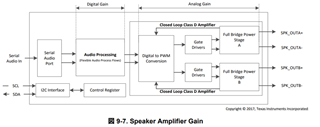
We are verifying the I2C communication of TAS5825.

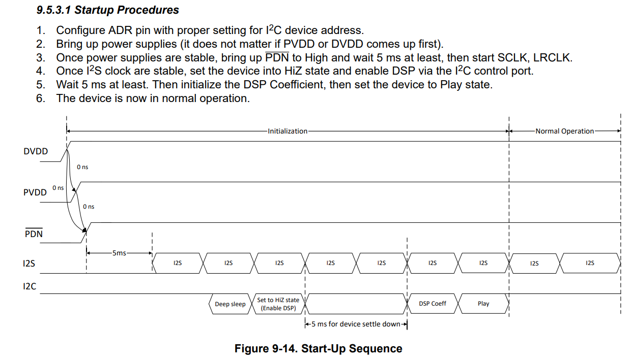
Page 42 of the datasheet describes "9.5.3.1 Startup Procedures", but I would like to confirm two points.

1. Is it correct that I2C communication becomes valid 5ms after *PDN is asserted to High?

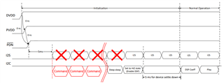
2. Is it correct to think that I2C and I2S are independent?

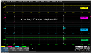
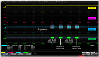
 I understand that "9.5.3.1 Startup Procedures" is just the I2S operation start sequence, and that I2C commands can communicate 5ms after *PDN goes High, as shown in red in the figure below. Is this recognition correct?

/* TAS5825M datasheet URL */

https://www.ti.com/lit/ds/symlink/tas5825m.pdf?ts=1707274089925&ref_url=https%253A%252F%252Fwww.ti.com%252Fproduct%252Fja-jp%252FTAS5825M%253FkeyMatch%253D%2526tisearch%253Dsearch-everything%2526usecase%253Dpartmatches

Regards,

MM

  • Hello MM 

    1. No this time is associated with internal LDO and voltages e.g. VR_DIG, I2S not valid without I2S on startup
    2. No, for this device I2S clocks need to be available to write I2C properly

    The TAS5827 doesn't have this requirement if that's a concern

    best regards,
    Luis

  • Hi Luis,

    Thank you for your support.

    We would like to confirm a few additional points.  

    1. Is the I2S clock defined as both “SCLK/LRCLK”?

    2. TAS5825M, Could you please tell us why an I2S clock is required when performing I2C access?

    *I2C and I2S appear to be unrelated in the block diagram listed in the datasheet.

    3. Currently, SCLK/LRCLK of I2S are not being sent before the timing of I2C access to the TAS5825M, but the I2C access is successful and the register settings are correctly configured.

    When you read the register after startup, you can read the written value.

    We have also confirmed that an ACK response has been returned.

    ・Wirte 0x03 to addr 0x03
    ・Wirte 0x80 to addr 0x78
    ・Wirte 0x1f to addr 0x54
    ・Wirte 0x3b to addr 0x4c

    Does this mean that these behaviors are out of spec, but are working by accident?

    We are asking these questions to see if we really need an I2S clock input.

    Just one point, the I2S in your answer is I2C, right?

    /* Your comment */

    No this time is associated with internal LDO and voltages e.g. VR_DIG, X I2S (O I2C) not valid without I2S on startup

    Regards,

    MM

  • Hello MM,

    The Block diagram doesn't show all the internal connections just demonstrates a simplified functional blocks to explain the internal structure of the device.

    The TAS5825 uses SCLK for internal clocks e.g. the PLL to generate higher frequencies within the device. Without SCLK the DSP may not work. Without SCLK you can config Page0 Book0 registers but tuning registers associated with the DSP won't work.

    best regards,
    Luis

  • Hi Luis,

    We would like to confirm the answer I received from you.

    (1)

    Are the "CONTROL PORT Registers" listed in the specifications the "Page0Book registers" you are talking about?

    (2)

    Our customer does not do any audio tuning.

    https://www.ti.com/jp/lit/an/slaa786a/slaa786a.pdf?ts=1707799535424&ref_url=https%253A%252F%252Fwww.ti.com%252Fproduct%252Fja-jp%252FTAS5825M%253Futm_source%253Dgoogle%2526utm_medium%253Dcpc%2526utm_campaign%253Dasc-null-null-gpn_jp-cpc-pf-google-jp%2526utm_content%253Dtas5825m%2526ds_k%253DTAS5825M%2526dcm%253Dyes%2526gad_source%253D1%2526gclid%253DEAIaIQobChMIq6SLm8CnhAMVKg97Bx3zOADMEAAYASAAEgLk7_D_BwE%2526gclsrc%253Daw.ds

     
    Audio tuning is done on the SoC (Host) side, and the TAS5825M is used simply as a digital input class D amplifier.

    Since the DSP tuning registers (Book 0x78, 0x8C, 0xAA) are not used, they remain at their default values, and the only initial settings are the register settings described in the previous reply.
    Even in such a case, do I have to follow the I2C access restrictions you mention?

    Regards,

    MM

  • Hello MM,

    1. Yes That's correct
    2. The clock is still used to generate the internal DSP clocks, your data will still go through the signal processing path that is dependent on this clock so it is still needed

    best regards,
    Luis

  • Hi Luis,

    As explained earlier, in our environment, it is possible to correctly write data to the specified address (0x03, 0x78, 0x54, 0x4c) from I2C even when the I2S clock is not input.

    However, since we received your response that this behavior is not recommended and that an I2S clock is required, we are considering sequencing.

    We have additional questions regarding clocks.

    (1)

    Item 4 of the Startup Procedure in the above diagram states "Once I2S clock are stable", but does I2S clock mean both SCLK and LRCLK?

    (2)

    Is there a clock pulse number or time as a guideline for "stable"?

    Regards,

    MM

  • Hi MM

    Item 4 of the Startup Procedure in the above diagram states "Once I2S clock are stable", but does I2S clock mean both SCLK and LRCLK?

    Yes, both clock.

    Is there a clock pulse number or time as a guideline for "stable"?

    The "Stable" means the clock frequency is fixed value, you could check your SOC in the system, how long time it needed to gives out fixed clock value. Needn't have additional waiting time after all the clock frequency fixed. 

  • I apologize for asking you to confirm so many times.

    We would like to confirm for the timing, so would it be possible for you to actually provide us with the waveforms of *PDN, I2C and I2S (SCLK and LRCLK)?

    Regards,

    MM

  • hi, MM

    as described in the datasheet, we recommend providing i2s before i2c be sent.

    but the i2s signal was not generated by amplifier, we can not define how fast the SoC can generate stable i2s. 

    currently, you can r/w by i2c w/o i2s is because those registers are all in page0 which described in the datasheet.

    if you config EQ, AGL or some other modules, those registers are in other book and page, the i2s clk is necessary. otherwise the configuration cannot be flashed into DSP.

    tks

    jesse

  • Hello Jesse,

    The customer only changes the AGAIN and DIG_VOL registers in Page0, and uses the other parameters at their default values.

    Furthermore, in the customer's startup procedure, AGAIN and DIG_VOL settings were changed from I2C before the I2S clock was input, and it is currently working without any problems, which led to this question.

    Even in that case, the final answer is that compliance with the startup Procedure described in the datasheet is mandatory, and no other exceptions are allowed, right?

    Regards,

    MM

  • hi MM

    do you mean below 2 registers:

    DIG_VOL Register: 4Ch

    AGAIN Register: 54h

    if only use the register at book 00 and page 00, the i2s has no need to provide first.

    does customer use our PPC3 to generate initial script? or they just refer datasheet to config the amplifier?

    usually, we recommend operate our amplifier using our PPC3 GUI, the tutorial is as below:

    /cfs-file/__key/communityserver-discussions-components-files/6/3364.How-to-Generate-a-Header-File-fro-TAS5805M-in-PPC3.pdf

    tks

    jesse

  • Hello jesse,

    That's right, the customer is using the TAS5825M with only the following two registers configured.

    DIG_VOL Register: 4Ch

    AGAIN Register: 54h

    We were relieved to hear that I2S clock is not required if only book00 and page00 are changed using I2C.

    I confirmed for PPC3 GUI, and I understand that it is software compatible with TAS5805MEVM, so if you don't have this evaluation board, it will be difficult to evaluate using PPC3, right?

    Therefore, the customer configures using data sheets.

    Regards,

    MM

  • hi MM

    our PPC3 can be used offline.

    you can config all parameters with our PPC3, then export the .h file.

    then flash the .h file to customer's board to perform the evaluation.

    tks

    jesse

  • Hello jesse,

    It make sense.

    We would like to take advantage of PPC3.

    Regards,

    MM