This thread has been locked.

If you have a related question, please click the "Ask a related question" button in the top right corner. The newly created question will be automatically linked to this question.

SRC4392EVM-PDK: software issues

Part Number: SRC4392EVM-PDK
Other Parts Discussed in Thread: SRC4392, SRC4192

Hi,

I am currently evaluating the SRC4392 module using its development-board.

Is the software necessary in order to test simple TOSLINK input to TOSLINK output configuration, or is jumper/switch solution sufficient in this matter?

Regarding the answer on the first question, the GUI and drivers for AIC310x has been recommended i various support threads but i cant make it work towards the hardware. Which steps do you recommend taking in order to make the software compatible with the hardware?

BR,

Joakim 

  • Hello Martin,

    I have not used this EVM specifically but i have  used another similar SRC device in the past couple of times and I recall I just used the switches on that EVM without using the GUI. 

    In general, when I need to run a script for an EVMs that needs its registers to be programed, most of the time I use a generic I2C read and writer and  run the scripts and  thus program the device that way . In specific I use PPC3 general I2C writer ( you can download it from ti.com) and use it to communicate with any device that takes I2C commands.

    So if you want to use a GUI for this device, I suggest to download PPC3 and use the I2C mater that comes with it  to write your script. Let me know if you have any question.

    Regards,

    Arash

  • Hello Arash,

    Thank you for your response. For the time being, GUI is not necessary. This does not solve the issue i am afraid.

    With JMP1 configured to enable TOSLINK input, the TOSLINK output pin on the daughterboard is completely dead. Are there any usual suspects regarding the board configurations of this behavior, or have I missed anything vital?

  • I forgot to mention that the mute SW is set to LOW.

  • Hello Martin,

    In general clocking is the first suspect, but I understand you are sending S/PDIF via TOSLINK. When I tested the SRC4192 EVM , I was using I2S   and I recall its  SCK  had to be connected via the BNC  connector and EVM  would not work with the SCK pin that was next to I2S pins.

    Have you monitored few test points  such as supplies  or flags (RDY, SYNC and ..., 

    Can you test it in  I2S format first - just to see if it starts at all ? I have not used this EVM but it might need initialization via script. 

    I have attached 2 scripts that I found for this part -in case you want to try it with script.

    Let me know if you are able to get it to work with any other format or/and with script. 

    .

    5164.Sample code to initialize SRC4392.txt
    The following sequence should be used to initilaize SRC4392.
    
    1. Apply power and external reset.
    
    2. Write all control registers on Page 0 except register 0x01.
    
    3. Apply MCLK, as well as any audio clocks desired for Ports A and B.
    
    4. Write register 0x01 on Page 0 to power up the desired blocks.
    
    5. Disable DIT buffer transfers by setting the TXBTD bit in register 0x08, Page 0, to a 1.
    
    6. Write 0x02 to register 0x7F to set Page 2 as the active page.
    
    7. Write data to the DIT C and U buffers on Page 2 as desired.
    
    8. Write 0x00 to address 0x7F to set Page 0 as the active page.
    
    9. Enable DIT buffer transfers by setting the TXBTD bit in register 0x08, Page 0, to a 0. 
    This will update the DIT TA buffer with the data written to Page 2 registers.
    
    Example for Implementation of above:
    
    1. External reset
    
    2. Setting control registers on page 0 (it's always register address first, then data [all values in hex])
    
      w e0  7f 00      //Set Register Page 0
      w e0  03 20      // I²S Port A: Clock Slave, 24 Bit Audio MSB, Output Signal from Receiver - NOT from SRC
      w e0  04 00      // I²S  Port A: MCLK Source = MCLK; MCLK Freq = 128x LRCLK (MCLK Freq other than 128x just for Master Mode operation)
      w e0  07 00      // Clock Start Output; Transmitter MCLK Divider == FPGA CLK / 128
      w e0  09 01      // Transmitter Channel State Update via SPI
      w e0  0d 00      // Receiver Input == RX1, Ref CLK RXCKI (ext.)
      w e0  0E 00      // Receiver Mute if No CLK, Superclock on ext. Pin, CLK Divider = 4
           // Receiver PLL Ref Clk according Data Sheet (Table 4, S.60)
      w e0  0F 22   
      w e0  10 00    
      w e0  11 00  
           //
      w e0  2D 02      // SRC Source == Receiver, ref. CLK FPGA
    
    3. Enable clock  (mclk, frame sync, sample clock)
    
    4.  w e0  01 37  // switch on SRC, Receiver, Transmitter, I²S Port A
    
    
    Here is the script for steps 5 to 9:
    
    
    w e0 08 08 // disable the DIT buffer transfer
    
    w e0 7f 02 // set page to 2
    
    w e0 2e ee // write ee to reg 2e on page 2
    
    w e0 2f ff //write ff to reg 2f on page 2
    
    w e0 7f 00 //change the page back to 0
    
    w e0 08 00 // enable the DIT buffer transfer
    
    w e0 7f 02 // switch back to page 2
    
    r e0 2e 01 // read back reg 2e on page 2
    
    r e0 2f 01 // read back reg 2f on page 2
    
    w e0 7f 00 // set page to page 0


    5164.SRC4392_sample code.txt
    # This code file  assumes a 24.576MHz master clock and then sets up Ports A and B for 96kHz 24 bit I2S output (master mode).  
    # This script will probably need to be tweaked some, but it should provide a good starting point. 
    # One thing to note is the MCLK reference chosen for Ports A and B and the DIR is "MCLK" pin, this may need to be changed to "RXCKI" depending on the application.  
    # When feeding the TAS and PCM devices make sure the MCLK for those devices is synchronous to the BCLK / WCLK being fed to them.
    
    2)  There is not set clock, I chose MCLK assuming that the MCLK pin will be fed with a clock. 
    
    3)  By writing register 0x01, you can power down different sections of the SRC individually for lower-power, without having to reset all the registers (pg 51 of the d/s).
    
    
    # RESET RESET THIS IS MASTER RESET FOR SRC (48kHz)
    
    # Page 0 = DEFAULT for Control
    
    # Write to page 0
    
    #
    
    w E0 7F 00
    
    # Register 01, Bit 7 = 1 resets to default
    
    d 100
    
    w E0 01 80
    
    # Delay 0.1 sec to allow part to reset
    
    d 100
    
    # Register 01, Bit 7 = 0 for normal operation
    
    w E0 01 00
    
    d 100
    
    # w E0 7F 00


    # Register 01, Bit 7 = 1 resets to default
    
    #----- Setup Port A/B ------#
    
    # 24bit I2S, Master mode, DIR source, at mute
    
    # Divide by 256, MCLK input source
    
    #
    
    w E0 03 69
    w E0 04 01
    
    w E0 05 69
    w E0 06 01
     
    
    #----- Setup DIR ------#
    
    #DIR Config 1
    
    # Input source: RX2 - S/PDIF RCA (default)
    
    #w E0 0D 09
    
    # Input source: RX4 - S/PDIF optical, RX_MUX = RX1
    
    w E0 0D 08


    #DIR Config 2 - default
    
    w E0 0E 01


    #----- Setup DIT -----#
    
    # DIT COnfig 1
    
    # Port A data in, DIv 256
    
    w E0 07 80


    # DIT Config 2
    
    # Default is to output to RCA
    
    # Commment out RCA and uncomment Optical for optical outputs


    #Output to RCA
    
    # TX - ON, TX MUTE - ON, Optical disabled
    
    #w E0 08 06
    
    # TX Mute - OFF
    
    #w E0 08 04


    #Output to Optical
    
    # TX - OFF, TX MUTE - ON, optical disabled
    
    w E0 08 03
    
    # TX MUTE - OFF
    
    w E0 08 01


    #----- PLL Configuration -----#
    
    # Set P=2, J=8, D=0
    
    w E0 0F 22
    
    w E0 10 1B
    
    w E0 11 A3


    # GPIO1 Config
    
    # GPIO1 = RCVR non-audio data
    
    w E0 1B 06


    # GPIO2 Config
    
    # GPIO2 = RCVR non-valid data
    
    w E0 1C 07


    # Power Status
    
    # Disable RCVR (/PDRX) and Port B(/PDPB) power down and enable All Function power down
    
    #w E0 01 14


    # Unmute Port A/B Output
    
    w E0 03 29
    w E0 05 29


    # Disable All Function power down (all blocks set by local control)
    
    w E0 01 3F

    Regards,

    Arash

  • Hi Arash,

    Voltage supply seems fine, RDY and Rx lock LEDs does however not light up at any moment.

  • Hi Martin, 

    Please try with I2S format and then with the scripts I sent. you need to go through these debug steps to figure out what might be the issue.

    Regards,

    Arash

  • Hello Arash,

    Sorry for the late reply regarding this issue.

    In order to initialize the EVM module over I2C with Purepath Control we would need an USB-to-I2C adapter from you. Is there any adapter you know that is compliant with the PPC3 software and this particular EVM-Board? If that is the case, I would like have one to be able to continue with the evaluation.

    Thank you.

  • Hi Martin,

    You don't need any USB  adaptor. I usually send the I2C code through the USB connection (J24 in this case ) via  a PC. In some cases I just use wires to send the I2C signals (a clock (SCL), and a data line (SDA)) from another board  and program another EVM  (J23 in this case)

    Note that there are some jumpers/switches that needs to be set for I2C (refer to tables in page 5 of user's guide) 

    If you connect the EVM to PC, it should appear as TI audio device  (where the speaker icon is in the bottom right corner .  You might  need to install the  TexasInstruments_USBAudio_v4.13.0_2017-08-21_setup file and you can find it in the zip file in the below link.

    https://e2e.ti.com/support/audio-group/audio/f/audio-forum/1247760/tas2563ybgevm-dc-purepath-console-3-v3-2-1-build-306-fw-v1-1-0-0-tas2563-evm-v3-02-usb-audio-driver-not-working-windows-10?keyMatch=TEXASINSTRUMENTS%20USBAUDIO%20V4%2013%200%202017-08-21%20SETUP

    Please also take a look at this thread.

    https://e2e.ti.com/support/audio-group/audio/f/audio-forum/798082/src4382evm-pdk-installing-the-usb-modevm-driver

    Regards,

    Arash

  • Thank you for the swift reply Arash,

    I will try this approach. The EVM does not appear as TI Audio Device, but "USB-AudioEVM". 

  • Hello Arash,

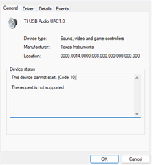
    After trying the approach suggested in the thread i get the following result.

    I've tried both UAC1.0 and UAC2.0, both with the same result. How can we move forward?

  • After hooking up the I2C pins to an oscilloscope, we can see the slave address when trying to use PPC3, but it does not send back an ACK resulting in a failed writing/reading.

  • Hi Martin,

     Recognizing it as "USB-Audio EVM" is fine  but I am not sure about the massage you see " device can not start with code 10."  May be the fact that it doesn't send ACK is related to the error of "device can not start , error 10".

    If you can not get rid of the above error, I suggest to open a new question for software support team without mentioning the part in the title ( so it doesn't come to me) Once the driver error is resolved, we can continue the debug here.

    Regards,

    Arash