This thread has been locked.

If you have a related question, please click the "Ask a related question" button in the top right corner. The newly created question will be automatically linked to this question.

SRC4392: Failed to power blocks on via reg 0x01

Part Number: SRC4392

Dear All,

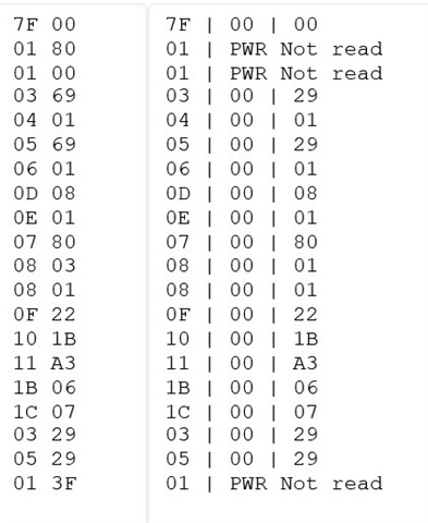
The problem is that I can write to all writable registers. Then read the values back no problem.

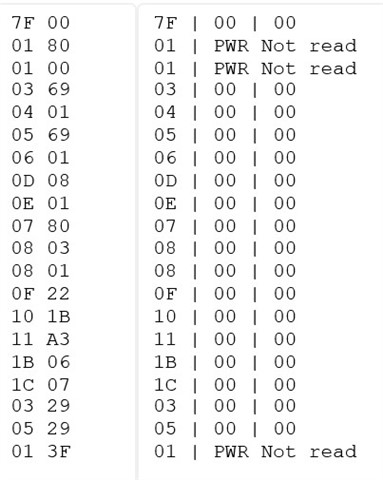
But when I want to power on a "block" by writing some value to reg 0x01 at page 0x00. Nothing happens. When I read back all the registers, everything is reseted to 0x00. I.e. all the once that where set and readback correctly in the first place and also the 0x01 register. So none of the blocks is powered on.

What could cause that I cannot power on any block at reg 0x01?

  • Hi Jan,

    As you know , there is a bit in  reg 0x01 called  RESET bit. This bit is used to force an internal reset, whereby all registers and buffers are forced to their default settings. Upon reset initialization, all functional blocks of the SRC4392 default to the power-down state, with the exception of the SPI or I 2C host interface and the corresponding control registers. 

    I attached here a sample code that you can refer to it.  

    0363.SRC4392_sample code.txt
    # This code file  assumes a 24.576MHz master clock and then sets up Ports A and B for 96kHz 24 bit I2S output (master mode).  
    # This script will probably need to be tweaked some, but it should provide a good starting point. 
    # One thing to note is the MCLK reference chosen for Ports A and B and the DIR is "MCLK" pin, this may need to be changed to "RXCKI" depending on the application.  
    # When feeding the TAS and PCM devices make sure the MCLK for those devices is synchronous to the BCLK / WCLK being fed to them.
    
    2)  There is not set clock, I chose MCLK assuming that the MCLK pin will be fed with a clock. 
    
    3)  By writing register 0x01, you can power down different sections of the SRC individually for lower-power, without having to reset all the registers (pg 51 of the d/s).
    
    
    # RESET RESET THIS IS MASTER RESET FOR SRC (48kHz)
    
    # Page 0 = DEFAULT for Control
    
    # Write to page 0
    
    #
    
    w E0 7F 00
    
    # Register 01, Bit 7 = 1 resets to default
    
    d 100
    
    w E0 01 80
    
    # Delay 0.1 sec to allow part to reset
    
    d 100
    
    # Register 01, Bit 7 = 0 for normal operation
    
    w E0 01 00
    
    d 100
    
    # w E0 7F 00


    # Register 01, Bit 7 = 1 resets to default
    
    #----- Setup Port A/B ------#
    
    # 24bit I2S, Master mode, DIR source, at mute
    
    # Divide by 256, MCLK input source
    
    #
    
    w E0 03 69
    w E0 04 01
    
    w E0 05 69
    w E0 06 01
     
    
    #----- Setup DIR ------#
    
    #DIR Config 1
    
    # Input source: RX2 - S/PDIF RCA (default)
    
    #w E0 0D 09
    
    # Input source: RX4 - S/PDIF optical, RX_MUX = RX1
    
    w E0 0D 08


    #DIR Config 2 - default
    
    w E0 0E 01


    #----- Setup DIT -----#
    
    # DIT COnfig 1
    
    # Port A data in, DIv 256
    
    w E0 07 80


    # DIT Config 2
    
    # Default is to output to RCA
    
    # Commment out RCA and uncomment Optical for optical outputs


    #Output to RCA
    
    # TX - ON, TX MUTE - ON, Optical disabled
    
    #w E0 08 06
    
    # TX Mute - OFF
    
    #w E0 08 04


    #Output to Optical
    
    # TX - OFF, TX MUTE - ON, optical disabled
    
    w E0 08 03
    
    # TX MUTE - OFF
    
    w E0 08 01


    #----- PLL Configuration -----#
    
    # Set P=2, J=8, D=0
    
    w E0 0F 22
    
    w E0 10 1B
    
    w E0 11 A3


    # GPIO1 Config
    
    # GPIO1 = RCVR non-audio data
    
    w E0 1B 06


    # GPIO2 Config
    
    # GPIO2 = RCVR non-valid data
    
    w E0 1C 07


    # Power Status
    
    # Disable RCVR (/PDRX) and Port B(/PDPB) power down and enable All Function power down
    
    #w E0 01 14


    # Unmute Port A/B Output
    
    w E0 03 29
    w E0 05 29


    # Disable All Function power down (all blocks set by local control)
    
    w E0 01 3F

    Regards,

    Arash

  • Dear Arash,

    Thanks for your answer. Yes I know. I never toggle that bit, always keep that one 0. So that is definitely not the cause of the problem.

  • Hi Jan, 

    Reset all the blocks first with 0x80 and then put them in power on 0x00 and see if there is a difference. Let me know what you find.

    Would you please send me the full script you are using so I can take a look at it as well?

    Thanks,

  • Hi Arash,

    Thanks for your answer! Sorry for the late reply. I don't know which tools you use in combination with the script. Can you tell?

    We have developed our own device (with the SRC on it) and tooling. I had to program the tooling in such a way that it handles the data in your script.

    What I now see is the following. I can program all registers. And I can read them back also (only reg 0x03 and 0x05 are changed). Except for reg 0x01 !!

    I can write but when I'm reading it back all registers are reset to 0x00.

    Below you see two screenshots. One where I program the registers with the values from your script. Left side are the values programmed. Right are the values read back (ignore the 00 in between).

    Then I only readback the 0x01 register. And after that all the other registers are read. You see in screenshot 2 that all registers now read 0x00 on the right side (ignore left side that's the old programmed data from screenshot 1). 

    So I have no idea if the blocks are turned on correctly or not because I can't read back the 0x01 register.

    Do you know why I can't read reg 0x01 without the SRC resetting everything?

    Screenshot 1

    Screenshot 2

  • Hi Jan,

    This is very strange that it can not  read register 01 and it changes the values of some registers. Looking at the 2 screens shoots, I would suggest to use a different I2C script writer such as I2C MASTER which  comes with PurepathControl3 (PPC3) and  you can download it  for free from ti.com. I always use I2C master as it is very simple and has never gave me any issue when i had issue with other GUIs I used.

    Regards,

    Arash

  • Hi Arash,

    Thanks we can give that a try. Now I have two question left. 

    1) Which hardware can we use best for the tool you recommended? We only need the I2C bus to our own board.

    2) Is it always possible to power on all blocks in reg 0x01, independent of the setting of that block(s)? Or are there situations (hw, reg settings, ...) in which case  it's not possible to turn on the power of (some) block(s)?

    Kind regards,


    Wilco

  • Hi Jan, 

    I connect the computer (that has PPC3 installed on it) via usb to the board/EVM (that has the device on it) and write the script using PPC3.

    Reg0x01 turns on all blocks, the configuration of each block can be achieved by their own dedicated registers as shown in register maps. So you need only reg 01 to turn them on or off.

    Regards,

    Arash