This thread has been locked.

If you have a related question, please click the "Ask a related question" button in the top right corner. The newly created question will be automatically linked to this question.

TPA3116D2: LC filter confirmation

Part Number: TPA3116D2

Hi,

I'm working on the TPA3116 amplifier. Config : Gain = 26dB, PVcc = 24V, RL = 2 Ohms, in PBTL mode.

- I'm able to have +90W but with THD = 7-9%. Is it normal to have that much THD to obtain near 100W ? 

-  Is the initial LC filter on the EVM board is obtimized for 20kHz-30kHz Vin band ?

- Do u have more customers applications using the PBTL mode (more than in the documentation) ?

Thank you!

  • Hi Sebastien

    I'm able to have +90W but with THD = 7-9%. Is it normal to have that much THD to obtain near 100W ? 

    Through calculation seems quite likely. The MOSFET Rdson and inductor DCR will divide voltage with your load, and Rdson value will increase a lot when device temperature goes up. It's quite likely output already have some clipping of your testing condition. If you increase supply voltage to 26V, the results should be better.

    Is the initial LC filter on the EVM board is obtimized for 20kHz-30kHz Vin band ?

    LC filter used 10uH+0.68uF. For PBTL 2ohm, 20KHz has -0.45dB, and 30KHz has -1.7dB derations. Seems acceptable.

    Do u have more customers applications using the PBTL mode (more than in the documentation) ?

    PBTL is quite normally seen.

  • Hi,

    Thank you for your reply.

    I've tried to use the TPA3116 on PCB, in the same configuration as before (PBTL,...) but with 2 LC filters (4 LC on the EVM). It seems like, for the same input and configuration, I've 50% power loss (50W output on the EVM = nearly 25W on the PCB).

    In sleep mode (without Vin), my PCB consumes slightly more power (0.8mA PCB vs 0.63mA EVM). With an input, the power supply consumption is 50% less than on the EVM.

    The thermal dissipation is quite different than on the EVM. Is it possible that this impact the power output? Will using a filter with 2LC instead of 4 affect this output power?

    Thank you!

  • Hi Sebastien

      If not changing the LC filter, it would quite similar with using half of the inductor value, but doubles the capacitor value. It's possibly additional heat is caused by the large ripple current on the inductor.

  • Hi,

    Thank you!

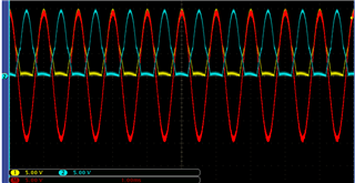
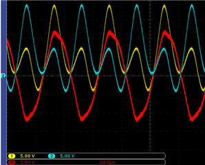
    I've tried the 1SPW mode with the EVM (initial LC filter) with 20dB, vin = 1 Vrms, PBTL. It seems like the output behaviour is related to the frequency (waveform).

    At 1 kHz :

    At 25 kHz:

    These signals are with the same input voltage.

    - Is the output signal at 25kHz normal (yellow and blue)? 

    - Can an other LC filter change the 25kHz signal as 1kHz signal? It looks like there is a pb at this frequency

  • hi Mavel

    25khz is very high which is larger than 20kHz, the inductor be used now need very good linearity to guarantee output performance.

    maybe u can take a try 4.7uH inductor to see whether increase cut-off frequency can improve this or not.

    tks

    jesse