


Hello all,
I am working on a new board that uses an PCM5121, it is connected to an ESP32S3 microcontroller.
Here is the schematic related to the PCM5121: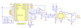
I would like (but there is no absolute need) to use the PCM as a slave. I try to play a sound in 44100hz with 32bit samples.
Since there is nothing fancy here I currently try to use the clock auto set feature that can be enabled with register 37.
I also disabled the PLL via register 4, set the DAC clock source to SCK and set the i2s format (register 40) to 0x03.
With everything set, I decode an mp3 file on the microcontroller and I am able to observe the clocks and signals with an oscilloscope :
- SCK : 11.4Mhz
- BCK : 1.4Mhz
-LRCK : 44.1kHz
These signals seems clean to me: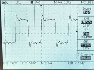
When playing, I am also able to see data on DIN. However register 118 "power state" remains always at 0001 :"Wait for CP voltage valid". It does not change when I am playing or not a file (data on DIN).
VNEG is also not at the expected value, it stays around 400mV.
Here are full dump of all registers:
reg 0x01 -> 0x00
reg 0x02 -> 0x00
reg 0x03 -> 0x00
reg 0x04 -> 0x10
reg 0x05 -> 0x01
reg 0x06 -> 0x00
reg 0x07 -> 0x00
reg 0x08 -> 0x30
reg 0x09 -> 0x00
reg 0x0a -> 0x00
reg 0x0b -> 0x01
reg 0x0c -> 0x7c
reg 0x0d -> 0x00
reg 0x0e -> 0x30
reg 0x0f -> 0x00
reg 0x10 -> 0x00
reg 0x11 -> 0x00
reg 0x12 -> 0x00
reg 0x13 -> 0x10
reg 0x14 -> 0x00
reg 0x15 -> 0x00
reg 0x16 -> 0x00
reg 0x17 -> 0x00
reg 0x18 -> 0x00
reg 0x19 -> 0x00
reg 0x1a -> 0x80
reg 0x1b -> 0x00
reg 0x1c -> 0x00
reg 0x1d -> 0x00
reg 0x1e -> 0x00
reg 0x1f -> 0x04
reg 0x20 -> 0x00
reg 0x21 -> 0x00
reg 0x22 -> 0x00
reg 0x23 -> 0x01
reg 0x24 -> 0x00
reg 0x25 -> 0x00
reg 0x26 -> 0xf3
reg 0x27 -> 0x04
reg 0x28 -> 0x03
reg 0x29 -> 0x00
reg 0x2a -> 0x11
reg 0x2b -> 0x01
reg 0x2c -> 0x00
reg 0x2d -> 0x00
reg 0x2e -> 0x00
reg 0x2f -> 0x00
reg 0x30 -> 0x00
reg 0x31 -> 0x00
reg 0x32 -> 0x00
reg 0x33 -> 0x00
reg 0x34 -> 0x00
reg 0x35 -> 0x00
reg 0x36 -> 0x00
reg 0x37 -> 0x00
reg 0x38 -> 0x00
reg 0x39 -> 0x00
reg 0x3a -> 0x00
reg 0x3b -> 0x00
reg 0x3c -> 0x00
reg 0x3d -> 0x64
reg 0x3e -> 0x64
reg 0x3f -> 0x22
reg 0x40 -> 0x02
reg 0x41 -> 0x00
reg 0x42 -> 0x14
reg 0x43 -> 0x05
reg 0x44 -> 0x00
reg 0x45 -> 0x00
reg 0x46 -> 0x00
reg 0x47 -> 0x00
reg 0x48 -> 0x55
reg 0x49 -> 0x00
reg 0x4a -> 0x00
reg 0x4b -> 0x00
reg 0x4c -> 0x00
reg 0x4d -> 0x00
reg 0x4e -> 0x00
reg 0x4f -> 0x00
reg 0x50 -> 0x00
reg 0x51 -> 0x00
reg 0x52 -> 0x00
reg 0x53 -> 0x00
reg 0x54 -> 0x02
reg 0x55 -> 0x00
reg 0x56 -> 0x10
reg 0x57 -> 0x00
reg 0x58 -> 0x61
reg 0x59 -> 0x00
reg 0x5a -> 0x00
reg 0x5b -> 0x36
reg 0x5c -> 0x00
reg 0x5d -> 0x20
reg 0x5e -> 0x20
reg 0x5f -> 0x00
reg 0x60 -> 0x01
reg 0x61 -> 0x10
reg 0x62 -> 0x00
reg 0x63 -> 0x00
reg 0x64 -> 0x00
reg 0x65 -> 0x00
reg 0x66 -> 0x01
reg 0x67 -> 0x03
reg 0x68 -> 0x07
reg 0x69 -> 0x00
reg 0x6a -> 0xd8
reg 0x6b -> 0x10
reg 0x6c -> 0x00
reg 0x6d -> 0x00
reg 0x6e -> 0x00
reg 0x6f -> 0x00
reg 0x70 -> 0x00
reg 0x71 -> 0x00
reg 0x72 -> 0x03
reg 0x73 -> 0x00
reg 0x74 -> 0x01
reg 0x75 -> 0x00
reg 0x76 -> 0x81
reg 0x77 -> 0x11
reg 0x78 -> 0x00
reg 0x79 -> 0x00
reg 0x7a -> 0x00
reg 0x7b -> 0x00
reg 0x7c -> 0x00
reg 0x7d -> 0x00
reg 0x102 -> 0x00
reg 0x105 -> 0x00
reg 0x106 -> 0x00
reg 0x107 -> 0x00
reg 0x108 -> 0x00
reg 0x109 -> 0x01
reg 0x2c01 -> 0x00
reg 0xfd3f -> 0x00
reg 0xfd40 -> 0x00
What could explain this behavior ?
Thanks for your help.
