Hi,
I have tried different sample codes from the forum and the internet but have not been able to get any output from the speaker.
Following are the commands i have prepared and correlated with the datasheet, all I2C commands execute fine and confirm the writes by readback.
Following are the sequence of write performed.
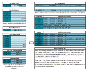
// Clock-gen muxing. PLL_CLKIN=MCLK, CODEC_CLKIN=PLL_CLK 12.288MHZ
// P=1, R=1, J=6, D=10000,
// NDAC=NADC=7, MDAC=MADC=3,
// DOSR=AOSR=384 => 16KHz fs

static const tlv_cmd_t init_cmd[] = {
    {0x00, 0x00}, // Page 0
    {0x01, 0x01}, // sw reset
    // PLL config
    {0x04, 0x03}, // Clock-gen Mux. PLL_CLKIN=MCLK, CODEC_CLKIN=PLL_CLK
    {0x05, 0x91}, // PLL P+R. PLL power up, P=1, R=1 (P=divider,R=multiplier)
    {0x06, 0x06}, // PLL J = 6
    {0x07, 0x27}, // PLL D fractional. D-value MSB = 0x27
    {0x08, 0x10}, // PLL D fractional. D-value LSB = 0x10
    // mode master
    {0x1B, 0x0C}, // mode is i2s master, wordlength is 16, BCLK/WCLK out
    // divider configs
    {0x0B, 0x87}, // NDAC is powered up and set to 7
    {0x0C, 0x82}, // MDAC is powered up and set to 2
    {0x0D, 0x01}, // DOSR = 384 0x180, DOSR(9:8) = 0x01
    {0x0E, 0x80}, // DOSR = 384 0x180, DOSR(7:0) = 0x80
    {0x12, 0x00}, // NADC divider is powered down and ADC_DSP_CLK = DAC_DSP_CLK.
    {0x13, 0x00}, // MADC divider is powered down and ADC_MOD_CLK = DAC_MOD_CLK.
    {0x14, 0x00}, // AOSR = 256 0x100, AOSR(7:0) = 0
    //
    {0x74, 0x00}, // DAC => volume control thru pin disable
    {0x44, 0x00}, // DAC => drc disable, th and hy
    {0x41, 0x00}, // DAC => 0 db gain left
    //
    {0x00, 0x01}, // Page 1
    {0x21, 0x4E}, // De-pop, Power on = 800 ms, Step time = 4 ms
    {0x1F, 0x84}, // HPL
    {0x23, 0x40}, // LDAC routed to HPL
    {0x28, 0x0E}, // HPL unmute and gain 1dB
    {0x24, 0x00}, // No attenuation on HP
    {0x25, 0x00},
    {0x2E, 0x0A}, // MIC BIAS = 2.5v
    {0x30, 0x40}, // MICPGA P = MIC M 10K
    {0x31, 0x10}, // MICPGA N = MIC N 10K
    //
    {0x00, 0x00}, // Page 0
    {0x3C, 0x0B}, // select DAC DSP mode 11 & enable adaptive filter
    //
    {0x00, 0x08},
    {0x01, 0x04},
    //
    {0x00, 0x00},
    {0x3F, 0x96}, // POWERUP DAC (soft step disable)
    {0x40, 0x04}, // Unmute DAC
    {0x51, 0x80}, // Powerup ADC channel
    {0x52, 0x00}, // Unmute ADC channel
    //
    {0x00, 0x01},
    {0x2A, 0x1C}, // Unmute Class-D left
    {0x20, 0xC6}, // Power-up Class-D drivers
};

static const tlv_cmd_t loop_back_cmd[] = {
    {0x00, 0x00}, // Page 0
    {0x1d, 0x1d}, // b4 = ADC-to-DAC loopback enabled
    {0x00, 0x01},
    {0x2e, 0x0a}, // MICBIAS = 2.5V
    {0x26, 0x4c},
};

static const tlv_cmd_t beep_cmd[] = {
    {0x00, 0x00}, // Page 0
    {0x40, 0x0C}, // mute DACs
    {0x0B, 0x07}, // power down NDAC divider
    {0x47, 0x80}, // enable beep generator with left channel volume = 0dB
    {0x49, 0x00}, // BeepLen HIGH
    {0x4A, 0x7D}, // BeepLen MID
    {0x4B, 0xA0}, // BeepLen LOW
    {0x4C, 0x59}, // BeepSin MSB
    {0x4D, 0x98}, // BeepSin LSB
    {0x4E, 0x59}, // BeepCos MSB
    {0x4F, 0x98}, // BeepCos LSB
    {0x0B, 0x87}, // NDAC is powered up and set to 7
    {0x40, 0x04}, // Unmute DAC
};
Following is the circuit diagram
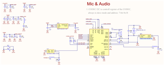 .
.
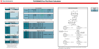
Following is the PLL calculation