This thread has been locked.

If you have a related question, please click the "Ask a related question" button in the top right corner. The newly created question will be automatically linked to this question.

PCM5120-Q1: PCM5120 Input ?

Part Number: PCM5120-Q1

Dear TI support team,

I intend to use PCM5120 as a MIC/ LINE In input as circuit draft below:

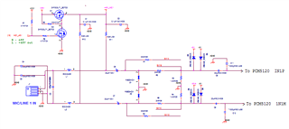
The J1 is a common jack for MIC and LINE Input. 

When MIC is selected, SW1 is ON so that R1 is in parallel to R5, R2 is in parallel to R6. When LINE IN, these switches are open.

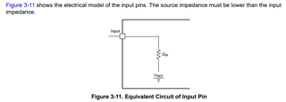
My question is: Is there a need of opamp as buffer before C8/C9 when they connect to PCM5120 input ?

Best regards,

SG

  • Hi SG,

    A buffer amp is not required, just ensure that your differential input signal does not exceed 2 Vrms or the absolute maximum ratings specified in the datasheet.

    Regards,

  • Hi Daveon,

    Thanks for your prompt response to my question. This makes my design simple.

    I guess you also mean that the input impedance is high enough so the LINE IN input impedance could just simply by summing R5+R3+R4+R6 (if the bias resistors are not taken into account) ?

    Does TI have any reference documents suggested for the fault protections caused by phantom power when a MIC/LINE ADC is in use ?

    Best regards,

    SG

  • Hi SG,

    To determine the impedance of your circuit you would have to take into account the capacitive/inductive reactance and resistance with relation to your input signal frequency. You may be able to determine this with an online simulation tool rather than by hand calculation.

    We don't have any documents on fault protection for phantom power. Are you asking about the typical circuit to bias an ECM microphone when supplying power from the device's MICBIAS pin?

    Also, please read:

    Working With Analog Inputs in the TLV320ADCX120 and PCMX120-Q1 Family

    This document has good insight to applications to the front end of our ADC as well as internal architecture.

    Regards,

  • Hello Daveon,

    Thanks for your further response.

    I took a quick look at the "Working With Analog Inputs in the TLV320ADCX120 and PCMX120-Q1 Family", and it mentioned that "The source impedance must be lower than the input impedance".

    Back to our last discussion, if I just place divider resistors in the input when LINE IN is selected, does this make it's input impedance very high ?

    BTW, 

    Your question: Are you asking about the typical circuit to bias an ECM microphone when supplying power from the device's MICBIAS pin?

    My answer: I am using norminal cadenser mic which may need a phantom power of 48V.

    Best regards,

    SG

  • Hi SG,

    The input impedance of your circuit is relatively low for each line of your differential signal. For instance, the impedance of IN1P from resistors is roughly [(2k*1.4k)/(3.4k)] ≅ 1kOhm. The impedance from capacitors and inductors (dependent on frequency) is also relatively low due to the value of caps used. Your current circuit looks to be okay. You can also program the input impedance of the device to be 2.5k, 10k, or 20kOhms.

    Your input signal is also AC-coupled due to the series capacitors prior to IN1P of the device. From the device view, all DC signal is blocked, so in the event phantom power surges through the input line, the device will be protected. Just ensure the capacitors are voltage rated correctly.

    This device does not have any integrated fault detection measures that exist in PCM6xx0-Q1 and TAC5xxx-Q1 devices.

    Regards,

  • Hi Daveon,

    Your comments ease my worries !

    Just to make sure if my understanding below is correct.

    Source impedance from 1N1P is roughly: (for LINE IN)

    2K//1.4K=2K*1.4K/(2K+1.4K)=0.824Kohm

    Unbalanced input impedance from capacitors and inductors is: (for LINE IN)

    (2K+1K4) = 3K4

    Best regards,

    SG

  • Hi SG,

    Resistance equation is correct. For capacitors and inductors, you'll calculate reactance using 1/(2*pi*f*C) and 2*pi*f*L respectively then use that with overall resistance to determine the overall impedance of each line. You can simulate in LTSpice or circuit simulation tool to verify. 

    Otherwise, as long as your input signal level is within the specified limits mentioned earlier, the device will operate as expected.

    Regards,